Categories Blog

Better than L70 for Interior Spaces?

Those of us who have been pushing solid state lighting for the past six-plus years are used to preaching about its benefits of high efficiency, fine optical control and expected lifetimes greater than anything else available.  Why?  Because from A-lamps to area lights, we need to communicate an intrinsic benefit to asking for the 2X-20X premium over the incumbent technology.  Outdoor lighting specifications, which have been predominantly based on HID sources, are quite rapidly changing to solid state lighting because a solid ROI can be communicated on those three aspects. It’s a tougher case for solid state lighting in conditioned interior applications where the efficient (and inexpensive) linear fluorescent is currently king. Solid state lighting manufacturers rely on the newly-attainable efficiency gains over fluorescent luminaires as the primary value proposition.  However, a rumbling of lumen maintenance claims as high as L90 are beginning to emanate from lighting manufacturers in an effort to add value to interior solid state lighting.  Is this all smoke and mirrors, or is there legitimate value for a L90 lifetime specification?

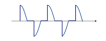
LED lifetime for general lighting applications is traditionally defined as the L70 lumen maintenance point, at which time the light output has depreciated 30 percent from its original value.  The industry settled upon this point for defining lifetime because it represented the threshold of the human eye for detecting reductions in light output.  Was this a little overzealous?  Probably, but we needed something.  At least with L70, there would be a perception of depreciation, although over the five-plus years of operation, it would be quite difficult to detect.  Should L90 ever be adopted, we’re essentially declaring end-of-life before the eye can ever see a difference!  Pretty ironic indeed.

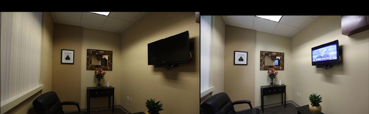
Admittedly, this is not new.  L90 is clearly in response to the newer 800 series T8 lamps that are claiming L90+ lumen maintenance over 40,000 hour-plus periods.  Should this be the benchmark?  Let’s keep in mind that these values are really only possible on a bench top.  A T8 lamp produces its peak lumens at a 25°C ambient and a T5HO at 35°C.  The problem is, the luminaire enclosure, surrounding optics and environmental ambient rarely, if ever, keeps the lamp even close to these temperatures!  A brand-new linear fluorescent troffer or suspended direct-indirect could, in-fact, begin its life well below L90, but this fact can be hidden in relative photometry.  Did we care (or even notice) then?

The temperature dependency of LED sources is why absolute photometry is specified by IESNA LM-79.  It certainly provides for more accurate light output from the luminaire, but it is not without its own demons that will be problematic for a legitimate L90 specification—that necessary evil known as binning.  Despite the diligent efforts of LED manufacturers to control their processes from die fabrication to packaging, all LEDs have some variation in terms of chromaticity and flux that must be tested and quantitatively grouped, or binned, into a predetermined range of values.  This range of values is usually a 10 to14 percent variation on flux.  The luminaire manufacturer then procures the LEDs to that binning specification, which will contain discrete LEDs of all values in-between.  On top of that, every LED manufacturer claims a measurement tolerance of 5 to 7.5 percent on their flux measurement.  All of this potential variation together means it’s very possible that a brand new LED luminaire will leave the factory well below L90!

Whether or not the products ship out of the factory at full output or below L90, there is a high probability that it will not be caught and relamped.  Why?  Because the only approved method for assessing LED luminous flux will be to test each product in an integrating sphere by a laboratory certified to conduct LM-79 testing.  To that extent, products will likely not even undergo a re-lamping at L70 since it’s still not to a point where users will find the lighting uncomfortable, let alone any clear indication that end-of-life has been reached.  Lumen maintenance is not a definite point in time that can be marked with a calendar—it’s a function heavily dependent on tens, if not hundreds, of variables not accounted for in any end-of-life projection.

L90 sounds really appealing on paper, whether it’s LED or fluorescent, especially within the game that is specification lighting.  When initial output and end-of-life lie so closely together and warranties are established around those qualities, that manufacturer is accepting a very high degree of risk in order to capture a bit of attention.  We can’t fault them for that, but let’s have a realistic expectation of what the technology is capable of providing and make sure there is actual value provided that offsets the risk. This isn’t uncharted territory.

Categories Lighting

The Difficulty with Daylight Hold-Off Controls

The call for improved energy efficiency and government/energy code requirements are driving a need for greater use of lighting control. One such example is the new federal requirement that all states adopt building codes that are at least as stringent as the most recent American Society of Heating, Refrigeration and Air Conditioning Engineers (ASHRAE) building code (90.1-2010) by October 2013.� That code requires automatic shutoff and dimming in many space applications, and will encourage numerous construction projects to go beyond that by connecting lighting systems to building management systems.

So, reducing electric lighting loads when daylighting exists makes sense, however, implementing this concept with the introduction of daylighting controls is not quite as simple. First, let’s take a look at the two types of daylighting systems; closed-loop and open-loop:

Open Loop: The photo sensor does not respond to, or “see”, the electric light that it controls.

Closed Loop: The photo sensor senses and responds to the electric light that it controls.


Closed loop systems are generally preferred since they adjust for any changes in the space and react and adjust to what is actually happening. For example, in a parking garage application one could have a situation where a series of daylight openings are blocked by large vehicles or a construction project where significantly less light is contributing to the space; an open-loop system would recognize the sun is out and dim the luminaires (incorrectly), whereas a closed-loop system would recognize the space is actually still very dark and would keep the fixtures at higher power to compensate for the blocked daylighting.

Open-Loop and Closed-Loop Sensors – Where Do We Put Them?
The difficulty with closed-loop daylighting controls is now we are asking the control system to understand how much of the daytime lighting contribution is from the luminaires, and how much the contribution is from the sun.

The challenges with open-loop systems are that the sensors are typically remote from the fixtures, and the system cannot account for variations in light. Many controls manufacturers have side-stepped this issue by utilizing an open-loop approach where the sensor resides in the luminaire, this is referred to as “Daylight Hold Off.”

Wattstopper, a lighting controls company, refers to this approach in their installation sheets as “Light Level Feature,”� which holds OFF and turns OFF lights when the space is occupied and adequate ambient light exists. When the light level drops below the set level it will turn the lights ON when the space is occupied. The factory setting is for maximum, meaning that even bright ambient light will not cause the sensor to hold the lights OFF if it detects occupancy in the controlled area. 

We know that open-loop systems measure the daylight contribution and alter the luminaire light output based on the readings from the photo sensor. Normally, an open-loop system has a sensor mounted so it’s in direct view of the daylight (see figure above), in other words remote from the luminaire. But in this case the photo sensor is in the fixture, how would that work?

Short Answer: Not very well.

Long Answer: An open-loop system must only read the daylight contribution in the space, so in order to accomplish this task while the sensor resides in the luminaire the sensor must wait until the luminaire is shut-off before the device can take measurements. At that point, when the luminaires are off, the sensor will take a reading and determine if the daylight contribution exceeds the user selected light level on the control — if the light level is, in fact, exceeded. Once the space is re-occupied, the system will hold the lights off, or in a lower level state.

If there is enough activity so the lights don’t shut-off, then this type of open-loop daylight control is rendered completely ineffective. An ideal application for hold-off controls would be in a small office. Conversely, in a space that has a lot of foot or vehicular traffic, this would be a poor application because it is conceivable, and in many cases likely, that the luminaires would not dim at all during the entire day.

The difficulty with closed-loop controls is the commissioning of the luminaires and the controls. Many closed-loop controls systems require that the controls are initially turned-on during the night so that the levels being read are only electric. While this is effective, it is sometimes very difficult to manage and can be costly because highly-paid technicians would need to attend the location after-hours.

Conclusion
The ideal solution is to have controls that work on the closed-loop principal – always measuring both electric and daylight levels simultaneously. Utilizing controls that can be commissioned for light level without technicians present after-hours provides the best scenario of easy and cost effective commissioning with accurate daylight harvesting control.

Categories Blog

Leading-Edge vs. Trailing-Edge Dimmers

The installed base of domestic dimmers supports the almost ideal resistance exhibited by the impedance of an incandescent bulb. These devices are increasingly called upon to support LED replacement lamps, which offer challenges unanticipated by the designers of the dimmer systems, such as low current draw and very fast luminous response to minor power fluctuations. This blog highlights how dimmer type determines both the selection of damper and bleeder circuits in LED drivers, and the switching topology needed to optimize operation.

Phase-cut dimmers, either leading-edge or trailing-edge, make up the bulk of the dimmer market. After the input voltage rises following the zero crossing, leading edge dimmers inhibit for a period of time, controlling energy transferred to the lamp load and hence output brightness. Trailing-edge dimmers also regulate output by inhibiting for a period of time, however this is referenced to the negative going edge of the half-cycle.

Leading-edge dimmers are typically lower cost and so are more widely used whereas trailing–edge dimmers exhibit lower EMI and are preferred in some markets (notably Europe) and noise sensitive environments. That-being-said, it is unlikely that the average consumer will know whether their fixture is controlled by a leading-edge or a trailing-edge dimmer, and so it is important that LED replacement bulbs work with both types.


Figure 1. Simplified schematic of a leading-edge phase-cut dimmer (Including transient and surge suppression elements LS and CS)


Figure 2. Simplified schematic of a trailing-edge, phase-cut dimmer


Why shimmering and flickering occurs in leading-edge dimmers and why leading-edge and trailing-edge dimmers respond differently
In leading-edge phase-cut dimmers, the switching element is typically a TRIAC. Unlike BJTs or MOSFETs the TRIAC will latch-on once it is energized (after forward current exceeds latching current). It will continue to conduct until the forward current drops below a threshold (holding current). The TRIAC is protected against input voltage surges by a bypass capacitor CS and from high transient currents at switch-on by a series inductance (LS). The installed base of TRIAC dimmers in use today are designed to work with an almost ideal resistance (an incandescent bulb). The bulb presents a very-low impedance during turn-on, latching the TRIAC (IF>>IL) and once in conduction allows current to flow to zero crossing which holds the TRIAC in conduction (IF > IH) for almost the whole AC half-cycle. With no capacitive or inductive elements, the incandescent bulb does oscillate when presented with the voltage step of a dimmed AC sine wave. Because the TRIAC-dimmer/incandescent-bulb interface is not sensitive to the LS and CS values, the values of these components are not constrained and vary significantly between different leading-edge dimmer designs.

At turn-on, an LED load presents relatively high impedance, so input current may not be sufficient to latch the TRIAC dimmer. In order to insure that IL is achieved, a bleeder circuit is typically added to the LED driver input stage. In the simplest form, the bleeder is a simple RC combination that insures a pulse of current when the input voltage is applied.

An LED lamp load does not exhibit incandescent-like pure resistance, and so, when presented with a step voltage the EMI filter and the bulk capacitance of the switching stage will cause an oscillation in the input current (IF) (see figure 3). The amplitude of the load ring is modulated by the surge protection capacitor CS, making the amplitude of the oscillation dependent on dimmer type.


Figure 3. Typical input current waveform for a power-factor-corrected dimmable bulb showing the oscillation caused by input current dropping below IH

To reduce the ring, a damper circuit is added – in its simplest form a series resistance to reduce the amplitude of oscillation at the expense of reduced efficiency (and therefore more heat for the LED bulb enclosure to manage).  The LED Bulb designer must add the smallest amount of damping impedance at the input stage of the LED that will allow the LED bulb to remain above the minimum holding current. Different leading-edge dimmers have different values for CS and LS which act to modify the current ring on the TRIAC. The TRIAC in each dimmer type will see more ringing than would be seen at the bulb due to LS. The designer must allow sufficient margin (give up efficiency) in the damper circuit to work with as many dimmers as practicable.

To further enhance damping, a bleeder is needed to compensate for, or mask the ringing below, the holding current. A simple RC bleeder is used across the input line or after the bridge rectifier. The bleeder is optimized with respect to the power rating of the LED driver. For lower power LED lamps higher bleed is required.

Trailing-edge dimmers present a different set of problems
The input voltage waveform from a trailing-edge dimmer is sinusoidal at the start of each half-line cycle. The MOSFET switch is driven by a controller which continually energizes the gate, making the dimmer less susceptible to current ringing.

However, the power supply in the LED will present a high impedance to the dimmer when the MOSFET switch is opened to cut power delivery. Trailing-edge dimmers require the input voltage of the LED driver to fall to zero each half-cycle to enable the dimmer controller to energize its own supply rails. This ensures that the zero-crossing detector will turn on the switch at the beginning of the next voltage half-line cycle. If there is insufficient impedance to bleed down the dimmers output voltage before the next AC cycle begins, then the dimmer may misfire causing shimmer and flicker.


Figure 4. For a trailing-edge dimmer if insufficient current is drawn to force a zero-crossing before the next half-line cycle, the dimmer may misfire, causing shimmer or flicker

Buck converters in particular have challenges when supporting trailing-edge dimmers. Buck converters are very popular for LED lamp drivers due to their high efficiency and low component count. For a buck topology, when the input voltage falls below the output voltage, the switching circuit cannot draw any power from the AC rail (and is therefore unable to bleed down the switch voltage). In contrast, buck-boost, tapped-buck and flyback converters can draw current for the entire switching cycle. For this reason, buck-boost converters and tapped-buck drivers with ICs, which switch through the whole line cycle as the LYTSwitch-4 from Power Integrations, can pull down the dimmer voltage after it turns off and are therefore better able to support trailing-edge dimmers.


Figure 5a. Buck Converter – Excellent with Leading-edge dimmers. MOSFET D-S is reverse biased when the input voltage drops below ~48 V. The passive bleeder (C8/R6) is required to provide the low impedance path between line-neutral to force zero crossing of the input voltage to work with trailing-edge dimmers.


Figure 5b. A Buck-boost converter continues switching (provides a low impedance) to the input when the input voltage has fallen below output voltage, making this topology more suitable for trailing-edge dimmers

Conclusion
Bleeder and damper circuits can be tuned to accommodate almost all leading-edge phase-cut dimmers. The designer trades off efficiency in order to achieve best possible dimmer compatibility but is not able to guarantee performance due to the variability of dimmer component values. Practical designs usually accommodate trailing-edge dimmers. In order to work with trailing-edge dimmers, further compromise on efficiency (large bleed current) or even a change in topology may be required in order to achieve acceptable dimmer compatibility in a given bulb design.

Categories Lighting

Reducing Flicker in LED Lighting

Nearly all AC-powered traditional light sources exhibit some degree of periodic modulation or flicker. Additionally, many traditional lighting sources produce a noticeable flicker as they near their end of life. Although desirable in some situations and not perceived equally by all people—both visible and non-visible flicker should be avoided, or at least minimized, in most lighting applications. Through its Cree Services Thermal, Electrical, Mechanical, Photometric and Optical (TEMPO) testing service, Cree has tested hundreds of SSL luminaires from streetlights to MR16 lamps to help characterize flicker and identify what levels of flicker are acceptable in certain situations, and how flicker can be minimized in LED lighting.

Metrics and Industry Standards
One of the greatest challenges with flicker is that an official industry standard does not exist to fully quantify the effects of flickering light sources. Visible flicker is usually noticed at frequencies below 100 Hz. The second volume of The Illuminating Engineer (1908) discusses the results of experiments to determine the “vanishing-flicker frequency” – the threshold where the effect is no longer observed. This is now known as the flicker fusion threshold or rate, and is influenced by six factors.

  1. Frequency of the light modulation
  2. Amplitude of the light modulation
  3. Average illumination intensity
  4. Wavelength
  5. Position on the retina at which stimulation occurs
  6. Degree of light or dark adaptation

According to the Illuminating Engineering Society (IES) RP 16 10 standard, percent flicker is a relative measure of the cyclic variation in the amplitude of a light source, and flicker index is a measure of the cyclic variation taking into account the shape of the waveform. The drawback to this method is that it addresses only two of the six factors previously mentioned. In addition, it assumes that a light source will always flicker at a fixed frequency and amplitude, and does not address random, erratic events that cause flicker, such as a sudden decrease in electrical current or voltage.

The ENERGY STAR requirement for lamps, due to go into effect Sept. 30, 2014, specifies that the highest percent flicker and highest flicker index be reported, but does not specify a maximum allowable limit for either.

Moreover, the Alliance for Solid-State Illumination System and Technologies (ASSIST)[1] defines flicker acceptability criteria based on their testing. Using the ASSIST criteria, at 100 Hz, percent flicker greater than 20 percent is unacceptable, and at 120 Hz, percent flicker greater than 30 percent is unacceptable.

Flicker in LED Lighting
Flicker is also nothing new with SSL. As a new technology, SSL is put under more scrutiny than the traditional light sources it is destined to replace, which is understandable after the many issues compact fluorescent lighting (CFL) had when it was first introduced to the market. Although our test results from a sample population of several SSL products show a wide range in flicker; a large majority of those products perform the same or better than other traditional light sources (to see the actual test results, read our white paper on flicker).

LED flicker characteristics are primarily a function of the LED driver. Most of the attention has focused on the ripple frequency that occurs on the output of the LED drivers, which is typically two times that of the input. For example, if the input voltage frequency is 60 Hz, the ripple frequency is 120 Hz. The light output of an LED correlates closely with the output waveform of its driver.[2] Figure 1 shows a waveform of the ripple current from a driver. Figure 2 shows the resulting waveform of the light output of an LED connected to the driver.[3] In this example, the driver ripple current fluctuates 46 percent and the resulting percent flicker of the LED is 36 percent.


Figure 1. Driver output ripple current


Figure 2. Measured Light Output


Flicker is also present with pulse width modulation (PWM), a technique commonly used to dim LEDs. Figure 3 shows the flicker index versus duty cycle for a square wave at three different modulation percentages. The worst case flicker index, with the value approaching 1.0, would be for a light that flashes in short, low frequency bursts.


Figure 3. Flicker index for square wave


Solutions to Flicker
A well-designed driver can reduce the perceived flicker produced by an SSL luminaire. If designing a custom driver for a luminaire, capacitance should be added to the output of the driver to filter out the AC ripple component; however, this comes with the trade-off of potentially decreasing system reliability, especially if low-quality capacitors are used. In many applications, such as replacement lamps, it may not be possible to add sufficient capacitance because of physical space constraints.

If a luminaire designer chooses to use a commercially available (i.e. off-the-shelf) driver, a driver that minimizes the amount of driver ripple current should be selected. If information on the percent ripple is not provided, it is important for a designer to get this data from the driver manufacturer before making a selection.

One cause of flickering is compatibility issues with dimming and control circuitry. It is important to specify and verify that the products are indeed compatible with the dimmers or other control circuits used in the lighting system. Problems can be caused by a faulty photosensor or timer.

Furthermore, random, intermittent flickering could be an indication of some other problem in the lighting system such as loose wiring and interconnections. Problems with the quality of the electrical supply can also result in power fluctuations. If those causes are suspected, it is important to investigate further to prevent any potential safety hazards.

Flicker index and percent flicker are typically not listed in product datasheets or labeling. Until they are, it is critical for the lighting designer to either obtain this information from the luminaire manufacturer or conduct luminaire testing to measure flicker directly.

Categories Blog

One Shade of Grey

HB-LED manufacturers do not sell bare die. There are several reasons for this, not least being that they are too small to be of any use except, perhaps, as a substitute for pepper in overpriced restaurants.  The solution that has evolved uses ceramic tiles called sub-mounts. The die is attached to one side of the tile with all necessary electrical connections made and a small lens is popped on top. On the underside of the tile are provided solder pads, connected to the die by vias. The solder pads permit the sub-mount and hence the HB-LED, to be attached to a PCB just like any other surface mount component.

Alumina is the ceramic of choice for LED sub-mounts. It is cheap, easy to drill and metallise, and has reasonable thermal conductivity (20-30 W/mK). It is also white. This improves luminaire efficiency by reflecting itinerant photons to beneficial directions.

Due to technical advances, HB-LED die are getting smaller and brighter. These two trends mean that both the amount of heat and the heat flux (W/mm2) produced by HB-LEDs is increasing. And LEDs do not like it hot. High temperatures reduce life, degrade the light quality and decrease the efficiency of light production which, incidentally, causes the LEDs to run hotter still.  But, as the power rating and power density of HB-LEDs climbs, alumina is unable to remove the heat fast enough. This has forced the industry to switch to aluminium nitride ceramic and caused sleepless nights for many an engineer and purchasing manager.

Aluminium nitride makes an excellent sub-mount for HB-LEDs on just one criteria; its thermal conductivity is nearly six times improved at 160 W/mK. But, it is much more difficult to manufacture and process, resulting in a price premium roughly 10 times alumina! And, to cap it all, aluminium nitride is available in precisely one color. Grey. Despite all the disadvantages, the need for high thermal conductivity sub-mounts has resulted in such a wholesale switch from alumina to aluminium nitride that the supply side is close to capacity. This means future pricing is going in one direction only.

Next-generation HB-LEDs will need sub-mounts with even greater thermal conductivity. Beryllium oxide would fulfill the need (330 W/mK), were it not for the minor annoyances that it is 10 times the price of aluminium nitride and ever so slightly toxic. Time for some lateral thinking.

Metals, like aluminium, are really good thermal conductors (205 W/mk) and readily available as thin, flat, sheets. However you can’t put circuits directly on a metal tile because everything would short. The solution is a dielectric surface coating and ceramics, like alumina, are excellent dielectrics. So, the ideal sub-mount for an HB-LED is a thick metal core to provide the thermal conductivity with a thin ceramic coating to provide the electrical isolation. Provided the ceramic coating is thin the thermal resistance of the layer will be negligible. Aluminium can be converted to Nanoceramic alumina in an electrochemical cell. The conversion can even be done on the sidewalls of holes making possible formation of vias. The result is a mechanically robust sub-mount, with thermal conductivity close to the best aluminium nitride available, but at a fraction of the cost and with no supply chain constraints. It should be no surprise that HB-LED manufacturers are busy tooling-up to use this new material.

While Nanoceramic has the interesting property that means the color can be tailored from white to black, there is no truth to the rumor that it can be purchased in 50 shades of grey to suit the intended disposition of the luminaire.

Categories Lamp

Improvements in LED Lamps

The LED lamp retrofit market continues to be a much sought after arena with more and more players entering the market. With an abundance of choices available, it is important to do your research to understand some key parameters of these novel light sources. This will help to find a LED lamp solution that not only fits your current needs, but also those in the future.

Have you ever wondered why the LED lamp that you just bought to replace your typical incandescent or halogen bulb is so much heavier? It is because of the need for thermal management in the LED lamp and the associated use of a heavy heat sink. Contrary to popular notion, LEDs do generate heat and unless that heat is dissipated properly in the lamp, the LEDs can heat up leading to lower lumens, lower energy efficacy, shorter lamp life and shift in color. Most LED lamps use a mass of shaped die cast aluminum as the heat sink material. However recent innovations in thermal management by some companies have enabled substantial reductions in LED lamp weight. This involves sophisticated thermal modeling and use of alternate forms of metal fabricated by different methods.

The LEDs in a solid state lamp are driven by DC but the socket into which the lamp is screwed is powered by AC. Electronics located in the LED lamp convert the AC into DC. Here, too, not all LED lamps are the same. Some innovative companies are using sophisticated electronic circuitry, which leads to high power conversion efficiency so that much less electrical energy is lost as heat in the circuit components and more is available to drive the LEDs. This leads to higher LPW (Lumens per Watt) and a more energy-efficient lamp.

The quality of dimming is another parameter that differentiates LED lamps from different suppliers. Robust dimming is the new trend among reputed suppliers who design their LED lamp electronics in such a way as to be compatible with a wide variety of leading edge dimmers. Flicker is minimized and the lower limit of dimming is on its way down to about 5 percent or less.

Many people love the warm tone that results when you dim an incandescent lamp. Do you wonder if this nice ambiance can be achieved by dimming a LED lamp? The answer is: yes, it can be done. Using advanced technology, a few forward-looking companies have recently introduced LED lamps with this special effect. This is essentially done by using proprietary algorithms to vary the current through two or more strings of LEDs of different color temperature using specially designed driver electronics.

How about effortless interaction with the LED lamps in your house? Would you like to switch your lamps on/off and dim them using a smart phone? Would you like to have the ability to do this remotely, say from your office? Would you like to set lamps in different rooms to different scenes? All of this is possible with wireless LED lamps. These lamps incorporate a radio frequency (RF) controller board in the lamp along with the driver electronics. A hub located in the house talks to the radio in the lamp using a wireless protocol like ZigBee and using a smart phone and the web, one can control all the wireless lamps in the house. Some innovative companies have recently introduced such lamps for the retail market.

It is important for the consumer to realize that not all LED lamps are created equal. LED lamps incorporate a wide variety of technical disciplines: materials, thermal management, electronics, optics, LED and process engineering. The best providers are able to design high performance into the product at a good value.

Categories Lighting

Historical Use of Glass in Lighting

Artificial lighting has been one of the most valuable technologies ever invented and commercialized, beginning with oil lamps in c. 4500 BC, street lamps in 900, Edison’s incandescent bulb in the 1870s and LED today. Now, with the widespread adoption of LEDs, lighting is again pushing technology, functionality, comfort and now energy efficiency forward to improve our daily lives. Despite the vital role glass has played for centuries as a valuable component of artificial lighting, however, it has been missing during the LED generation and gone largely unnoticed.


Infographic by Designbysoap

Glass has been a constant presence in lighting since lanterns and street lamps first appeared on the scene in the 1700s, providing protection to both the lighting source (oil or gas) and those in close proximity to it, creating both a functional and safe solution. The incandescent bulb came along at the start of the 20th Century, becoming the essential shroud around this new jewel of lighting that would dominate and reinvent the world over the next 100+ years, providing an inert vacuum environment to protect and sustain the lighting source for long life and reliability. With the commercialization of high-performance High-Intensity Discharge (HID) and Mercury vapor commercial lighting technologies, such as High-Pressure Sodium and Metal Halide in the 1950s, glass served an added protective function along with projecting the light source. Glass was then and is now a translucent, durable material with the ability to provide light transmission while offering long-term protection to and from a light source emitting high levels of Ultraviolet (UV) and Infrared (IR) energy that would easily degrade a lesser material. In addition, the thermal strengthening or tempering of glass provided and extra measure of safety in case of breakage in the field. This partnership of light source technology and glass allowed for HID-based commercial lighting in applications such as sports and entertainment; roadway, street and area lighting; and industrial areas to flourish for the next 50 years.

At the turn of the century, as it happened a century earlier with Edison, an exciting new lighting technology began to make its way into the market. Although the first LED was invented in the early 1960s, its relevance as a viable commercial lighting source did not appear until the early 2000s with high-brightness GaN LEDs on silicon substrates. Not since Edison’s incandescent bulb have we have seen such a technological revolution and paradigm change in the lighting industry. LED lighting offers superior performance, flexibility, and energy efficiency for a wide variety of applications. Ironically, production of Edison’s original technology is now in the final stages of phase-out in the United States, and the LED is poised to be the incumbent technology going forward.

However, a funny thing happened along the way to LED lighting’s dominance – glass was left behind.

Unlike traditional incandescent and HID light sources, LED as a light source in a luminaire:

  • Generates its illuminance pattern combinatorially from an array of individual point sources of light (LED chips) patterned together with individual optical lenses instead of one single source (bulb) and a reflector array with a single lens
  • Does not generate high levels of UV and IR energy that degrade many translucent lens materials.

As a result, many lighting designers and luminaire OEMs have elected to field LED-based fixtures with only plastic lenses (acrylic, polycarbonate, etc.), with the belief that glass is no longer a necessary component of a luminaire – even for outdoor applications. The common belief is that glass no longer provided a tangible benefit in the field vs. plastics – especially in LED lighting, where UV and IR energy levels are low. Another argument is that a glass lens decreases the efficiency of a luminaire due to reflection losses.

On the contrary, history has shown glass to be the best long-term lens material choice for commercial lighting applications – especially those in outdoor or industrial environments. Glass protects the valuable components of the luminaire (light source, optics, drivers and ballast) from environmental elements – regardless whether it uses HID or LED technology. Unlike standalone plastic lenses, glass:

  • Does not carry a static charge which attracts dirt and debris, resulting in the depreciation of the luminaire over time
  • Is mechanically and chemically durable to resist degradation due to scratching and salt water exposure along coastal areas, and yellowing due to environmental UV exposure
  • Can be thermally or chemically strengthened for safety in case of breakage
  • Is a low-cost and readily available material option
  • Can be modified through glass chemistries (low iron), applied coatings (anti-reflective, conductive, etc.) and surface treatments (acid-etching, patterning, etc.) to optimize optical performance.

History has taught us that no material is perfect. However, throughout the history of lighting, glass has repeatedly proven to be a worthy, valuable and reliable product for a variety of light sources. When paired with LED lighting and plastic-based primary optic lenses, glass can indeed provide even more differentiated value into the same commercial lighting applications it has for more than 100 years. In the blogs ahead, I will discuss in more detail the innovative ways the industry can use glass as a lens material in this new and exciting world of LED-based lighting.

Categories Energy

New 2016 Energy Code Impact on Commercial LED Retrofits

Before changing any of their lights to energy saving LED technology, commercial building owners and tenants need to fully understand the new 2016 regulatory impact of mandatory lighting efficiency upgrades in 41 states and Washington, D.C.

The regulations were set in motion back in March of 2015, but the cost burdens will start to sting in 2016. The new commercial building energy codes are equal to or better than ASHRAE 90.1 2004 (BCAP 2015a) –  American Society of Heating, Refrigerating, and Air-Conditioning Engineers. These codes require changing lights, in part because commercial illumination is over 20 percent of any given building’s electricity costs and it is the “low hanging fruit” of energy reduction.  Reducing waste in lighting through Light Emitting Diode (LED) technology is more economically viable than creating renewable power through Solar or Wind production.

Who Dodges the Lighting Change Bullet?
The codes impact the majority of the US. Over the past decade, only 11 states have lagged behind the rest regarding statewide energy codes. Alaska, Arizona, Colorado, Wyoming, North Dakota, South Dakota, Kansas, Missouri, Arkansas, Mississippi, and Maine were still using 2006 IECC codes when the other states adopted 2009 and 2012 standards – International Energy Conservation Code.

What do I have to do if I am a commercial tenant, or if I own a building?
If you improve a space that requires changing 10 percent or more of the light fixtures then you may need to change ALL of the fixtures within the space to meet the new standards. Most importantly, the ubiquitous 3-lamp fluorescent tube fixtures with T8 tubes are no longer acceptable. You have to use more energy efficient fixtures to meet the new watts-per-square-foot requirements. Your options include LED tubes and fixtures, T5 fluorescent and potentially T8F25 with Energy Star ballasts fixtures. Since LED tubes have increased dramatically in efficiency over the past five years and come down in cost, the change is less painful than it would have been previously. Except for spaces with only one fixture, multi-level switching and occupancy sensors are now required in all areas.  You also need to have the occupancy sensors that can be set in vacancy mode. All spaces within 15 feet of windows must be equipped with daylight sensors with dimming or multi-level controls.

The $0 Cost Solution:
You don’t have to buy new lights. Many financing options are available, and some LED manufacturers and solutions providers will “lend” you the lights and structure a Lighting Service Contract. This Lighting as a Service (LaaS) kills two birds with one stone. You can meet the new code requirements and you reduce your monthly operating expenses, all without spending a dime.

Top Tip on Energy Code Impact:
Work with a commercial LED lighting solutions company that knows the new codes in your market or knows enough to ask the questions that will prevent any buyer’s remorse.  This will help you avoid spending money twice or opening a can of worms that you regret.

Categories LED

New PCB Materials for Thermal Management of High Brightness LEDs

Despite the enormous efficiency advantages of LEDs, when compared to incandescent lights, they still waste around 70 percent of the electrical energy put into them. This energy appears as heat and needs to be conducted away from the LED to maintain a safe operating temperature. Overheating an LED severely limits its lifespan and impacts on efficiency and color quality.

Existing thermal management technologies are limiting the speed at which LEDs can penetrate into certain high-powered application areas. They simply cannot deliver the technical performance required at acceptable cost.  Huge opportunities therefore exist for companies that can find a more cost-effective substrate solutions for high brightness LEDs.

Conventional Approaches
The key characteristics required for a thermal substrate are excellent thermal conductivity and good electrical isolation. This limits the materials choice. Aluminum nitride (AIN) has traditionally been used in high brightness chip on board (COB) LEDs and as a submount for high power LEDs.

Whilst aluminum nitride is thermally more than up to the job the exotic manufacturing process – requiring carbonthermal reduction of aluminum oxide or direct nitridation of aluminum, together with the extremely high temperatures involved – makes it very expensive. Currently available machinery limits the size that can be manufactured to around 4 inches by 4 inches. It is also quite brittle, which in turn limits the yield. Add to this the requirement for specialist processors and you end up with a very uneconomical product.

The use of aluminum itself is a very compelling option – it’s a great thermal conductor, cheap, readily available and extremely robust. What it lacks is electrical isolation. The standard approach of adding an epoxy to the surface to produce a dielectric layer reduces the thermal conductivity too much for use with high brightness LEDs so an alternative is needed.

Attempts to anodize the surface of aluminum to combine the thermal conductivity of aluminum with the dielectric properties of a ceramic have failed repeatedly over the years – the anodizing process leaves gaps in the dielectric layer, which can create electrical short circuits.

A New Approach:
Cambridge Nanotherm has taken a new approach, patenting an entirely original electrochemical process for creating a dielectric on the surface of aluminum. This process produces a composite substrate with thermal properties comparable to AlN but far more cost effective.

Nanotherm’s approach converts the surface of a sheet of aluminum into a dielectric nanoceramic layer. The crystals formed can be as small as 30 to 60 nanometers. Because the nanoceramic is formed by a conversion process, this ensures a perfect and robust bond between the dielectric and the aluminum resulting in a uniform layer of ceramic, which is a perfect dielectric.

The nanoceramic dielectric layer can be as thin as 3 microns, this makes the thermal path between the LED chip and the aluminum as small as is feasibly possible, resulting in extremely high overall thermal conductivity.

What’s more the nanoceramic layer can be grown just as easily on complex 3D shapes. This is key to the creation of vias. With AIN, creating vias is expensive, complex and creates mechanical weakness. With the Nanotherm process, holes can simply be drilled in the aluminum before processing and the ceramic dielectric will be deposited uniformly on the surface of these through-holes.

The Result:
The resulting nanoceramic dielectric layer has a thermal conductivity of around 7.2 W/mK and a dielectric measure of about 50 V/um. For COB LEDs, the finished product has a thermal conductivity of 152 W/mK (measured between the top surface of the copper that carries the wiring trace and a 0.6 mm aluminum sheet). This outperforms many low-grade and mid-grade AIN products.  Double-sided metallization, with through-holes yields sub-mounts for LEDs.

Cost is always a factor. With an industry in desperate need of finding ways to bring the cost of LED products down to a point that the mass market are comfortable with, any saving is good. Not only do nanoceramic substrates offer a significant cost advantage over AIN, they can also be processed through standard PCB manufacturing facilities, bringing the scale and cost advantages of the traditional PCB industry to bear on the LED packaging market for the first time.

Nanoceramics open up an entirely new class of thermal management aimed squarely at the high power LED market.

Categories Lighting

LED Grow Lights Reshape Agriculture

For photosynthesis, plants use more red  and blue wavelength light than green light within RGB full spectrum.  LED technology enables the delivery of only the wavelengths that are needed most, resulting in reduced electricity operating cost to “feed” the plants and increased ROI of plant harvests.

The next decade offers many opportunities for LED manufacturers, distributors, installers, and the whole host of energy professionals and solution providers. Saving energy and money is the key driver in the adoption of LED lights with high ROI and low Total Cost of Ownership (TCO). Low operating costs and low equipment costs move the needle.  For LED grow lights, the market is about making more of something vs less of something. More plant growth often trumps energy savings!

While LEDs can reduce the operating expense over metal halide and fluorescent grow lights, the real win is when the LED grow lights can shave 10 percent or more off of the grow time to harvest. As an example with lettuce or basil, the average grow time is about 30 days, and LED lights can accelerate the growth to deliver the same harvest weight in 27 days. Over a year, the farmer can deliver 13 harvest cycles vs just 12. One more harvest is meaningful. A 20,000 sq. ft. grow operation (about half an acre and half the size of a football field) can yield over $1.5 million in basil every year. Now, LED lights are about production vs reduction.

Here are some insights about the 21st century that provide perspective on why the LED Grow Light market is poised for dramatic market growth:

The Challenges:

  • Global population has doubled to over 7 billion since the first Earth Day in 1970.
  • Humankind may deplete fresh water resources before running out of fossil fuels.
  • In America, food travels hundreds and thousands of miles to its destination in many areas.
  • America faces increasing health challenges from childhood obesity and an overweight population.
  • Low-income households are at the highest risk, given limited access to affordable fresh produce.
  • The developing world faces increasing food challenges, given droughts and extreme weather.

The Solutions:

  • Leverage the advantages of Light Emitting Diode (LED) technology to provide cost-effective, fresh and organic produce at local levels.

Results:

  • Fresh and Cost-Effective Food for the World.

LED Grow Lights = $ Money. The available LED technology and “Smart Controls” enable next generation farmers to grow indoors during the day and at night. They also reduce shipping costs to increase net profit. LEDs will reshape agriculture, because a new generation of urban farmers will use abandoned and un-leased industrial buildings to grow organic food close to the communities that will eat it. This reduces the farm to table distance and cuts the pesticides out of the process.

Not all LED Grow Light are created equal.
If you are in the market to use LED grow lights or seek to expand your sales offerings through a strategic relationship, look for grow lights that meet certain standards. Specifically, look for LED Grow Lights with highest Photosynthetic Active Radiation (PAR) per dollar for vegetation and flowering.

In addition to LED vegetation and flowering fixtures, look for manufacturers that offer custom solutions to meet growers’ needs. Modular design can deliver Photosynthetic Photon Flux Density (PPFD) at varying wavelengths to give growers a competitive advantage.

Look for external driver technology with the ability to program, through smart controls, the cycles to optimize plant growth over multiple growth sessions within a 24 hour period, based on the different types of plants.

Look for fixtures with dimming capabilities to simulate sunrise and sunset and/or to optimize plant growth over multiple growth sessions.

Look for adjustable suspension systems so that the elevation of the light source above the plants is optimized for plant growth.

Look for opportunities to integrate hydroponic and also aquaponics systems into the LED grow operations.  A pound of feed may only yield an ounce of protein from livestock, while a pound of feed for fish will yield closer to a one-to-one pound of protein from a fish, such as tilapia.  Plus, vegetables such as kale are nutrient rich “superfoods” with numerous health benefits: http://advancingyourhealth.org/highlights/2013/09/17/health-benefits-of-kale/

Top Tip on LED Grow Lights:
Choose a commercial LED lighting manufacturer or solutions provider that has the highest Photosynthetic Active Radiation (PAR) per dollar of fixture cost. While higher watts are a negative in building illumination, they are typically a positive with grow lights (all things equal in the wavelengths), because more watts translate into more light for plant growth. The $/watt analysis is also relevant in comparing LED fixtures if the light of the different fixtures is distributed across the grow surface rather than creating hot spots. You can look at the cost per watt as a way to short list LED Grow Lights. Just divide the fixture cost by the wattage and this is a great first line of comparison.