Categories LED

Narrowing the Field of LED Luminaires


You know it’s a hot topic when the Wall Street Journal is writing about it. A few weeks ago, the WSJ wrote about a LED manufacturer’s product qualifying for utility rebates through the DesignLights Consortium (DLC). So what makes this so newsworthy? With the prices of LED luminaires already decreasing over the years, the opportunity for end-users to receive utility rebates for upgrading to energy efficient LEDs really helps shorten the ROI and drive more adoption of this technology. Essentially, utility rebates are lowering the upfront cost of new energy efficient lighting.

What is the DLC?
For those of you not aware, the DLC is collaborative effort between utility companies and regional energy efficiency organizations, to help buyers implement improved design practices in all areas of the commercial lighting market. According to their website, “the DLC promotes quality, performance and energy efficient commercial sector lighting solutions through collaboration among its federal, regional, state, utility and energy efficiency program members; luminaire manufacturers; lighting designers and other industry stakeholders throughout the US and Canada.”

Throughout its 17-year history, the DLC program has driven the lighting market towards innovation by providing information, education, tools and technical expertise for cutting-edge technologies. Since 2010, the DLC has administered the Qualified Products List (QPL), a leading resource that distinguishes quality, high efficiency LED products for the commercial sector. Today, the QPL sets the bar for efficiency program incentives across the US and into Canada while informing manufacturer product development.

Utility Rebate Programs
Utilities offer two types of rebate programs: prescriptive and custom. Prescriptive rebates provide a set amount for each fixture replaced. The dollar value of custom rebates is based on the total energy savings of a specific project.

In a report by Groom Energy and GTM Research, Enterprise LED 2012: Commercial and Industrial Market Trends, Opportunities and Leading Companies, utilities across the country show limited prescriptive rebate support for LED lighting. However, as the LED market matures, utilities will aggressively start moving. Additionally, this report states, “When satisfied that savings can be successfully achieved, utility program managers will typically authorize custom rebate amounts of up to 50 percent of the entire cost of the project, as opposed to a prescriptive rebate for each fixture.” And some of this is already occurring at a rapid pace. For example, New York is second only to California in dollars spent by utilities in energy efficiency rebate incentive programs. According to an article in Green Tech Efficiency, in 2008, there was approximately $3.1 billion available in total US rebate dollars, with the money concentrated in 10 states. The figures are expected to more than double in the coming years, with $7.4 billion to $12.4 billion available by 2020.

California, New York, Florida and Massachusetts have some of the most robust energy efficiency programs, but others, according to the Consortium for Energy Efficiency, like Pennsylvania, Illinois, Arizona and Ohio, have started building new programs entirely, North Carolina and Michigan are also increasing spending, according to the Lawrence Berkeley National Laboratory.

MORE on LED REBATES
The most accurate resource for energy rebates and incentives is the Database of State Incentives for Renewables and Efficiency, which is available online here. It details a comprehensive list of rebates and programs by federal, state and utility companies to help buyers determine whether projects qualify for rebates and incentives. It’s also a dependable resource for energy professionals and lighting distributors to use as a cross check against the DLC lighting lists.

Do Your Homework
Typically, when retrofitting with LEDs or choosing to install LED luminaires in new construction, the facility manager or building owner will hang a number of lights from different manufacturers for comparison. While this is an important part of the lighting selection process, reviewing the DLC’s Qualified Products List and the Database of State Incentives for Renewables and Efficiency streamlines fixture choices and aids in making the best decision.

Categories LED

LED Match Making – The Value of Photometric Analysis

Many commercial building owners and operators may have more light than they need in certain areas and less light than they need in other areas. When considering an LED retrofit, do not just buy new lights for the energy savings, but take the time to get the right type of lights to meet your business operating needs. Photometrics Analysis is a great way to “see” a plan and elevations of the current foot candle light levels and the potential to increase or decrease levels where needed.

As an example, for a national auto service chain, Monro Muffler and Breaks, one of the managers at a Connecticut location spoke about the need for more light in the service bays to show customers what needed to be fixed on their cars. The managers also spoke about a brighter more appealing overall look to their service centers to attract more customers. For a top BMW dealership in Virginia, the requests included improved light quality to showcase the vehicles. They wanted customers to be able to see the vehicles with brighter light and with color temperatures to more closely match how the vehicles appear outside in daylight. Since color temperature is measured in Kelvin and Kelvin impacts output in lumens, the lumens impact the foot candles. A photometric analysis helps shape the optimal lighting solution. In another example, an Anheuser Bush beer distributor, in Pennsylvania, with over 300,000 sq. ft. wanted to ensure 30 foot candles at the floor as well as on the storage racks. They wanted to be able to load the trucks more quickly with fork lift truck operators clearly seeing the palette labels under brighter light. In this case, the photometric analysis included both floor plans and elevations. The results of the study drove the inclusion of reflector systems where appropriate on the LED high Bay light fixtures. In each of these examples the right amount of light played a role in improving the operations of the business not just a reduced energy bill.

To better understand photometric analysis, here are some highlights from Wiki.

Photometry is the science of the measurement of light, in terms of its perceived brightness to the human eye.It is distinct from radiometry, which is the science of measurement of radiant energy (including light) in terms of absolute power. In modern photometry, the radiant power at each wavelength is weighted by a luminosity function that models human brightness sensitivity. Typically, this weighting function is the photopic sensitivity function, although the scotopic function or other functions may also be applied in the same way.

The human eye is not equally sensitive to all wavelengths of visible light. Photometry attempts to account for this by weighing the measured power at each wavelength with a factor that represents how sensitive the eye is at that wavelength. The standardized model of the eye’s response to light as a function of wavelength is given by the luminosity function. The eye has different responses as a function of wavelength when it is adapted to light conditions (photopic vision) and dark conditions (scotopic vision). Photometry is typically based on the eye’s photopic response, and so photometric measurements may not accurately indicate the perceived brightness of sources in dim lighting conditions where colors are not discernible, such as under just moonlight or starlight. Photopic vision is characteristic of the eye’s response at luminance levels over three candela per square metre. Scotopic vision occurs below 2 × 10−5 cd/m2. Mesopic vision occurs between these limits and is not well characterized for spectral response.

Based on this description above, the net of the photometry science is that it is more complicated than most business owners or operators care to learn. So, the tip below is as simple as working with the right people to navigate the complexity.

Top Tip on LED Light Matching with Photometrics:
Choose a commercial LED lighting manufacturer or solutions provider that has the software to run photometric analysis on your facility before making a major LED purchase. This gives you the power to review your options with objective data laid out in easy to review, multi-color floor plans and elevations.

Categories Lighting

Optimizing Lighting Efficiency with Glass

In last month’s blog post, I kicked off a series of about glass in lighting by providing a brief history and mentioned possible ways in which glass could effectively be used to increase lighting performance.  In particular, how it can be modified through glass chemistries (low iron), applied coatings (anti-reflective, conductive, etc.) and surface treatments (acid-etching, patterning, etc.) to optimize optical performance.  In this blog post, I want to continue the series by reviewing and discussing each of these areas in more detail to provide a more comprehensive understanding on how glass can be wisely used to optimize lighting efficiency in lighting applications.

The first major challenge of using glass as a material in lighting is with its inherent material properties.  Glass, as a material, loses 9 to 10 percent of lighting efficiency through reflection and absorption losses as shown in the graphic below.


Diagram courtesy of Guardian Industries


As you can see, 4 percent of light is lost through reflecting off of the first surface, another 2 percent lost through absorption from the FeOx content (0.11 to 0.08 percent) in standard soda lime glass chemistry, and still another 4 percent lost through reflecting off of the second surface.  In today’s world of high-efficiency and high-efficacy luminaire requirements, this is an unacceptable sacrifice and has unfortunately caused glass to be designed out of many lighting fixtures.  However, there are innovative and readily available ways to address this problem with glass and reduce reflection and absorption losses and increase overall light transmission and efficiency. These include using:

  • Low Iron Soda Lime Glass;
  • Anti-Reflective (AR) Coatings; and
  • Surface Treatments and Textures.

The use of low iron soda lime glass attacks the 1 to 2 percent absorption losses mentioned above by reducing the FeOx content of the glass chemistry down to 0.2 to 0.3 percent and all but eliminates absorption losses.  The spectral graph below compares the transmission curves at NADIR (0 degree incident angle) of standard soda lime glass and low iron glass with special attention given to the visible range where luminaires perform in:


Diagram courtesy of Guardian Industries


You can clearly see a boost of 1 to 2 percent of light transmission gained just from the replacement of the substrate material itself with low iron glass.  However, that still leaves 8 percent of lost light transmission due to reflectance losses to recover to gain optimum luminaire efficiency.  How can that be undone?

Anti-Reflective (AR) coatings can be effectively used to reduce reflection losses and increase light transmission in lighting as well as many other commercial applications.  In fact, they are already commonly used in eyeglasses, picture frames, and photovoltaics.  The principle of AR coatings is to minimize the interference of light traveling through a given material’s surface versus that of its immediate surrounding environment (in this case, air).  Therefore, the goal of an AR coating with a glass lens in lighting is to create this interference layer with a refractive index (n) as close as possible to air (n = 1) and the glass surface (n = 1.52) to filter the reflection losses and bridge that optical gap.

Adding a 3-layer AR coating (medium, high, and low index gradient) to a low iron substrate, mentioned above, allows most of the 8 percent reflection losses to be recovered in light transmission and efficiency.  The spectral graph below compares the transmission curves at NADIR (0 degree incident angle) of standard soda lime glass and low iron glass as well as application of an AR coating on one (singled sided or SS AR) and both (double sided or DS AR) sides of the low iron glass (again with special attention given to the visible range where luminaires perform in):


Diagram courtesy of Guardian Industries


A reduction of reflection losses from 4 percent down to 0.5 percent per surface can clearly be seen and allows a Low Iron substrate with Double-Sided Anti-Reflective coatings to reach 99 percent light transmission (efficiency) in the visible range.  The absorption and refection losses seen earlier with using standard soda lime glass have been all but removed at the 0 degree incident angle.

But what about angular losses in light transmission? Since most LED-based luminaires are dispersing light in very aggressive light distribution patterns there is limited value in maximizing light transmission at a 0 degree incident angle only.

The combination of Low Iron glass and AR coatings also help with the reduction of angular losses as shown in the material output files from LTI Optics of standard soda lime glass, low iron glass, and Single-Sided and Double-Sided AR coatings on low iron glass:


Diagram courtesy of Guardian Industries

Where:  τ = Transmission, α = Absorption, and ρ = Reflection

As these plots show, the average light transmission achieved with standard soda lime glass from 0 to 75 degree incident angles is only 86 percent whereas low iron reaches 88 percent, SS AR on low iron 90 percent, and DS AR 94 percent and holds > 90 percent light transmission up to 55 degrees (when standard glass only reaches that at 0 degrees).  Clearly, the combination of low iron glass and AR coatings help reduce angular light losses as well.

Finally, another method of reducing reflection losses with glass is by modifying its surface texture.  There are two commercially ready methods of doing this:

  • Acid-etching the surface to make the glass “frosted” or “diffuse”; and
  • Texturing (or patterning) the surface while the glass is still in its molten form.

Comparing standard clear glass (as a reference) to various acid-etched and textured products combinations (with and without an AR coating), you can clearly see benefits of modifying the glass surface to increase your light capture over angle with all cases providing superior performance versus standard soda lime glass:


Chart courtesy of Guardian Industries

In summary, glass indeed has some inherent challenges for effective use in the high-performance and energy-efficient LED luminaires of today.  However, with the use of innovative glass chemistries (low iron), coatings (AR), and surface modifications (acid-etch, texturing) these challenges can not only be removed but also allow for even higher levels of efficiency and efficacy to be achieved.

In my next post, I will provide some case study examples of effectively using these innovative uses of glass lenses, which provide both performance and economic (ROI, TCO, etc.) benefits in selected applications.

Categories Lighting

LED Optics – Beam Angle Counts for Warehouse Aisle Lights Now More than Ever

An ongoing trend for Distribution Centers and Warehouses across the storage market is narrower aisles and higher ceilings.  The driver for the trend is about revenue per square foot. Owners and operators have the ability to store and sell more products if they pack in those products to areas that occupy less of a footprint.

This trend creates opportunities for the LED market to support the storage businesses at new levels. Old technology like metal halide fixtures distribute light to the sides as well as down. Fluorescent tube fixtures typically do the same. These “WIDE” beam angle fixtures waste a lot of the light in areas where it is not needed. Reflector kits on multi-tube T8 or T5 fixtures help reduce the wasted light going up and to the sides but they largely still deliver “WIDE” output.

Optics help LED high bay fixtures deliver “NARROW” beam angles. Look for LED high bay fixtures that maximize the light output with optics to direct the light where you need it most.  Save money by wasting less energy and review fixture costs relative to useable output.


High Bay Performance: Watts, Lumens, and Foot Candles
A Metal Halide High Bay with a 400 watt bulb (up to 450 watts with the ballast factor) may deliver 36,000 lumens of which only 24,000 are directional. The foot candles on a ceiling with 25’ x 25’ grid may come in at about 30 fc.

A Fluorescent High Bay with 6 Tube High Output (HO) T5 tubes at 54 watts each (total 324 watts) and a reflector kit may deliver 24,000 directional lumens and the 30 fc to replace the Metal Halide High Bays.

An LED High Bay without reflectors or optics at 216 watts may deliver the 24,000 directional lumens and the 30 fc to replace the Metal Halide and the Fluorescent High Bays.

An LED High Bay with reflectors may only needs 162 watts to deliver 18,000 “narrow focused” directional lumens to achieve the same 30 fc.

An LED High Bay with optics may only needs to draw 108 watts to deliver 12,000 “ultra-narrow focused” directional lumens to achieve the same 30 fc.

The key here is for buyers to understand that they should not just shop for high bays based on lumens. Buyers should definitely not disqualify LED high bays that have less lumens without looking into the reflectors and optics. The economic impact is significant as the wattage consumption decreases with more advanced technology:

  • 450 watt Metal Halide
  • 324 watt Fluorescent
  • 216 watt LED
  • 162 watt LED with Reflectors
  • 108 watt LED with Optics


The level of optics is determined by the ceiling height, the width of the aisles, and the foot candle needs at the floor and at the racks.


Understanding the loading process for fork lifts helps provide perspective on the width of the aisles:

  • Wide Aisle (WA) lift trucks operate in aisles that are 12’ on average. They are the standard counterbalanced lift trucks that have become synonymous with the term “fork lift”. Wide aisle trucks generally operate in aisles greater than 11’ for handling 48” deep loads.
  • Narrow Aisle (NA) lift trucks operate in aisles 8’ to 10’ across. This is primarily the domain of the stand-up reach and double-deep reach trucks.
  • Very Narrow Aisle (VNA) trucks generally operate in aisles of less than 6’ and often use guidance systems (wire, rail, optical) to travel within the aisles. Standardized VNA vehicles consist of man-up order selectors used to manually handle less-than-pallet-load quantities and man-up turret trucks used to handle unit loads.

Top Tip on LED Light Matching with Photometrics:
Choose a commercial LED lighting manufacturer or solutions provider that has high bay and /or aisle light fixtures with options for optics to focus the light down to where you need it most. Check the foot candle output at the horizontal work surface and on the vertical storage racks so that lift operators can see the products clearly. Overall, go beyond selecting a short list of fixtures by lumens or lumens per watt and look into the foot candles per watt and also the foot candles per dollar for the fixture cost.

Categories LED

Tipping Points, Toothaches and LEDs (?)

Scene 1: A toothache had me sitting in a comfortable endodontist’s chair, surrounded by state-of-the-art dental equipment. The smell of paint and new carpeting, in addition to soothing music, was in the air, and the lighting quality was both very good and comfortable. To avoid thinking about a possible root canal, I distracted myself by listing what I thought was lighting the space without looking up. I started noting my observations in my head. CCT was warm (probably 3,000 K), very good CRI (probably 90+), high R9 (good skin tones, certainly positive, maybe by a lot), high scalloped shadows on the wall (several “smaller” fixtures?), well-blended lighting on the walls a couple of feet below the ceiling line (not CFLs, probably linear sources), very uniform light at work surface heights throughout the entire space, no intense glare sources showed in the highly reflective equipment surfaces (definitely not CFL). I could hear someone coming so I quickly wrapped up my lighting audit. I guessed the room was lit with 3,000 K T5 fluorescent lamps in quite a few good volumetric lighting fixtures, possibly 4-foot but probably shorter, and probably not HO.

Scene 2: After explaining the need for an immediate root canal and readying the appropriate tools and supplies, the soft-spoken endodontist said, and with way too much enthusiasm, “We have reached the tipping point!” as I was reclined into position. From my new vantage point, to my surprise, I could clearly see 2 by 2, two-lamp, U-lamp, T12 fluorescent lamps and fixtures. I didn’t see that coming.

Scene 3: Prognosticators have recently said that the “LED tipping point” is behind us; therefore, why isn’t this newly-equipped, recently-renovated, state-of-the-art office lit with LEDs? Many likely think the explanation is complex, but I think it is pretty simple. Prognosticators come and go, but “lighting” evolves.

Scene 4: “Lighting technology” is mostly important to “technologists,” whereas, a reliable, cost-effective and comfortably-lit space is what is important to the customer. LEDs are a light source technology and not a lighting product or solution. LEDs can and will enable reliable, cost-effective and comfortably-lit spaces, but that won’t happen overnight. Have we forgotten the trials, tribulations and time it took to “evolve” from T12 to T8, from magnetic to electronic ballasts, or from T8 to T5?

Conclusion: Comparing that which comprised the fluorescent “evolution” of the past 30 years to the “evolution” awaiting us in/with solid state lighting is simultaneously exciting and sobering to those who understand the potential benefits, business opportunities, added functionality and challenges which might come along with solid state lighting.  I look forward to the day when my house recognizes my approach and turns on my porch light to minimize my key fumbling, when sensors recognize me beginning to sit in my favorite chair and turn on my reading lamp to a high intensity/warm color, and when those same sensors recognize me dozing and dim that reading lamp to a much lower intensity. I am excited about a future where concepts like this surround us in the workplace. Although I wouldn’t classify most consumers and users as “technologists,” it is clear to me that most can be aggressive consumers of “technology” with smart phones, tablet computing devices and cars that parallel-park themselves being only a few examples. The work will be challenging, but interesting. The benefits will initially be difficult to document with numbers, but nonetheless evident. Patience (by all) will be required but exciting times and opportunities lie ahead for lighting that leads.

Categories Lighting

Smart Lighting – Removing the Power Burden

Smart Lighting – One of the major benefits of solid-state lighting (SSL) is that it is very controllable. The advent of highly responsive LED lamps and an increasing ability to control brightness and color are giving rise to an imaginative new era in lighting design. The spectrum of innovation today includes context-aware lighting, lighting that reacts to user activity, and smart lighting systems that adjust to human requirements. The aim of these new lighting regimes is to increase productivity. But before implementing such a system, productivity benefits must be weighed against the cost of complex control systems and computing engines as well as the ability to manage power. SSL was first introduced with the goal of reducing power consumption and this remains central to the realization of the concept. Unless designers adeptly manage the power budget, any gains of these new systems could be wiped out.

Context-Aware Lighting – One type of leading-edge lighting system today takes account of user activity within a room and is known as context-aware lighting. Room occupancy sensing is not a new idea, but the increase in sophistication has taken the concept way beyond a motion-activated, on-off switch. With today’s technology, a lighting system can detect the presence of multiple occupants in a room and use their relative positions to deduce what the group is doing (eg., watching a presentation, drawing on a white-board, or simply working on a computer). The lighting system then provides lighting appropriate for that activity. This is certainly impressive, but does require significant computing power and numerous sensors that track the positions of multiple occupants continuously, and then infer their actions from their location and motion.

For this system to work acceptably for the room user(s), each of the sensor and lighting nodes must always be ready and react quickly to data inputs and commands and to provide data to the system – a delay of more than 500 ms is generally considered unacceptable for a lighting system to respond. Typically, a fast-wake from standby requires power to be continuously delivered to each node in the system. Therefore, controlling the amount of power consumed by smart lighting devices while they are inactive is very important if smart lighting is to deliver the power savings partly necessary to justify its expense.


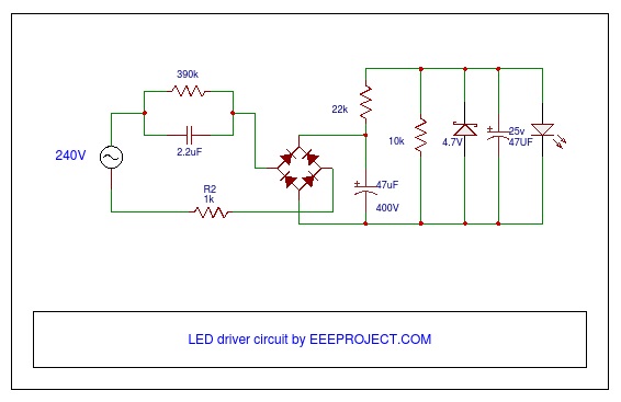
Simple single-stage bulb driver


Simplified view of a multi-output-stage LED driver

Powering Smart Lighting Systems in Standby- SSL systems are typically powered by AC mains (either 115 VAC or 230 VAC) or, in some cases, using Power over Ethernet (PoE – IEEE802.3at and later derivatives under development).

Computer and telecom rack systems have standby power consumption in the order of 180 – 250 mW but are “network aware” with approximately 3 W of consumption. There will not be very many control hubs in the system so their power drain in quiet mode can typically be ignored.

Sensors and luminaires are another matter. A context-aware lighting system in an average sized conference room may use 20 motion sensors and 20 adjustable light sources. Even with a standby power consumption of 1 W per device this equipment will consume power equivalent to an incandescent bulb left permanently on – far from ideal if you are aiming to save power and reduce waste heat.

Therefore, deep sleep modes and power supplies that can efficiently deliver very low power will be necessary. The drive towards low power consumption in power adapters for cell phone chargers (currently less than 30 mW in no-load) means that it is now possible to keep power consumption low with existing low power drivers. LCD monitors in sleep mode consume approximately 100 mW while delivering 25-30 mW to control circuits that are able to monitor the PC interface looking for a wake-up signal.

Drivers that use less than 10 mW in standby mode are achievable (some are already in use in the TV and appliance market). Managing even the 40 nodes described above could therefore consume less than 0.5 W if the sensors can run in a zero-load mode.


Ultra-low, no-load/standby power supply


The LED lighting market has always had separate commercial/industrial and consumer requirements. Consumers need low cost and fast payback from LED bulbs and small luminaries. Commercial customers can take a longer term view, trading increased fixture cost for large luminaires against increased efficiency and reduced maintenance cost. It is therefore not hard to see that smart lighting will first see significant deployment in commercial applications where the increased infrastructure cost can be more easily accepted.  Care must be taken to limit standby power consumption in each power stage, lest the advantages of high efficiency are allowed to literally leak-away via many devices and sensors waiting in standby mode.

Categories Bulb

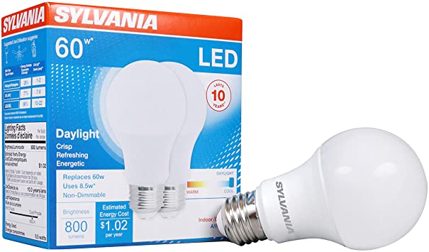
Latest 60 W Equivalent LED A19 Bulb for $2.49

For a limited time, one major local home improvement retailer in the United States is offering a non-dimming 60 W equivalent LED A19 type bulb for $2.49 each, sold in a two bulb value pack manufactured by a major LED maker. Similar types of bulbs were about 6x the cost a few years ago. With price drops like this, we tend to see articles and discussions about the fall in LED bulb prices over the past few years, performance comparisons to previous versions on lumens/watt trends, or teardowns and investigations into the cost of materials etc. I decided to do a teardown to look at the design changes that went into this bulb to drive down cost versus an LED bulb from just a few years ago.   The trends to note from this perspective have been ongoing, but then the question to ask ourselves as designers is where will the basic design of an LED bulb step to next?

Figure 1 is a picture of the $2.49 bulb and as you can tell I was not trying to be pretty about the heat sink and casing as I was more interested in the driver at first.  It requires 8.5 W for a 60 W equivalent at 800 Lumens A19 bulb.


Figure 1. $2.49 A19 60 W Equivalent LED Bulb


Figure 2. Older A19 60 W Equivalent LED Bulb for comparison


Figure 2 shows the teardown from a bulb taken apart a few years ago, it cost $15.99 but I promised not to get into a LED pricing reduction analysis.  By the way, it required 8 W for only a 40 W equivalent at 450 Lumens A19 bulb.

To begin with, removing the plastic “optics” used to require a heat gun, but now days most of the time you can pry the plastic cover from the heat sink base.  Then simply remove a few screws and release the driver inside the casing. In older bulbs, there was still potting material inside the casing surrounding the driver along with a series of interlocks holding the casing to the heat sink.  Potting material is still used today, but I am considering general trends in the construction of LED bulbs.  The new bulb weighs around 49 g total, the old bulb heat sink alone is 70 g so for the same input power to the bulb, the heat sink is smaller and there is no potting around the driver. The number of LEDs went from 18 to 11 with the lumen output almost double. I did not measure the LED voltage on the old string, but I measured over the 60 V SELV limit on the new bulb as safety is now achieved from the mechanical housing not through electrical isolation from the driver.  Therefore, it’s obvious that lower weight, less LED counts, better materials or materials that function good enough can all contribute to lower cost.

The driver is more interesting.  The old driver was an isolated flyback design.  The controller has power factor correction, but what is not shown in Figure 2 is the added expense of having to cut the printed circuit board along the primary to secondary isolation boundary for safety creepage and clearance. The new driver is non-isolated and does not use a controller, but a set of discrete components.  The new driver has a smaller EMI filter and even the transformer is smaller. The BOM count was 53 or so in the past versus 27 or so today – this will reduce cost and improve reliability in the driver. [1]

Clearly, the trend is to reduce the driver electronics besides the material changes and efficiency of LEDs.  So where are drivers for LED bulbs going next?  Integration: but there are discrete designs that use the low cost components without the need for an integrated analog controller that provides good enough performance. NPN transistors in place of MOSFET transistors, better EMI filtering, fuses part of the printed circuit board, etc.  Non-isolated designs: when thinking about this trend and reducing component count the idea of Direct AC LED topologies can reduce the component count further and possibly eliminate some of the lower reliability electrolytic capacitors.

But how do these observations enable a smart LED solution?  Lighting is evolving from something used to see or read, but is becoming a user experience: warm dimming, color tuning, communication to control, visible light communication to guide us, sensors that interpret implicit human movement or environment changes, etc.  The latest low cost LED Bulb is a pathway to enable the technologies to take lighting into the future by reducing not just cost, but by pushing the boundaries on how we think about the construction of the bulb and how we challenge conventional thinking about consumer electronic design.  As a semiconductor supplier, the need is to stay ahead of the curve by providing the building blocks to make these future lighting applications realized, how many suppliers are there that can provide these building blocks? I know of one that is developing the building blocks to advance lighting into the smart future. [2]

Categories LED

Driving an LED Load

In this month’s article, we address factors that influence how an LED is driven, including different driver techniques and why they are preferred for a variety of lighting applications. We look at the effects of different loads, as well as control options to drive LED loads effectively.

Constant Current or Constant Voltage?
LEDs typically require a constant current rather than a constant voltage to operate. The LEDs themselves present a constant voltage drop across the line (although the actual value of the voltage drop varies between approximately 3.2 V and 3.0 V depending on LED type and temperature).

Constant current drivers (CC) deliver a constant current to the load across a range of LED voltage conditions. For bulbs, the driver is typically designed to deliver constant current across a narrow LED voltage range (perhaps nominal voltage +/- 10 percent). These drivers are very effective in tightly specified designs (such as LED bulbs), making them application specific. However, this approach requires the design of a dedicated CC power supply.

Another approach is to use a driver that can deliver a constant voltage (CV) across a wide current range. Many CV drivers are fully isolated, simplifying the design process and removing much of the burden of meeting safety approvals, it also facilitates scalability  by adding more parallel LED strings.

In order to maintain a constant current through the LED string with a CV output (such is often delivered from ballast-type drivers), a series resistor is added, the value for which is determined by the equation:

where VDC is the nominal output voltage from the power supply, VLED is the voltage drop across the whole LED string and ILED is the desired LED forward current.

This is a very simple relationship, but the effect of circuit tolerances becomes significant. Output voltage ripple and the voltage tolerance of the driver result in dramatically increased effects in LED circuits compared to similar low-voltage drivers used for more conventional power applications.  For example, although a voltage variation of  +/- 5 percent is not large when considering the output voltage, in an LED driver with a load resistor, ILED varies according to the amount of change in the difference between driver voltage and the LED voltage – the effect on output current is magnified.

In order to achieve an acceptable design, the engineer must trade off power dissipation in the resistor against output current variation.

The human eye is relatively insensitive to light intensity and adjacent drivers subject to similar input voltage and ambient conditions tend to track each other (the difference between drivers in the same conditions will be less than the worst case described above). Therefore, in fixed or consistent conditions the effect of the tolerance in a CV LED driver may not be a major concern, provided that output voltage can be controlled within a relatively narrow range.

Primary and Secondary Control – Performance vs. Cost
To drive an LED load effectively with a CV driver, output regulation must be well controlled. Secondary side controllers that directly measure output voltage and deliver correcting information to the primary side switching stage will tightly control the output but will also add cost and shorten product lifetime (the opto-isolator, which is used to transfer information from secondary to primary, degrades over time).

In contrast, primary-side controllers do not directly monitor the output stage. Instead, they infer output performance using indirect means. A challenge with this approach is that component variation can affect output regulation. Leakage inductance in the isolation transformer can easily vary by ±15 percent in production, which will significantly degrade the output tolerance of a design.  In order to improve accuracy, primary side-controllers (such as LYTSwitch-2 LED driver ICs) use correction algorithms to compensate for inductance variation as well as line and load effects. Thus, they can achieve output regulation of better than 5 percent across line and load.


Figure 1. Load and line regulation in voltage mode for LYTSwitch-2 LED driver ICs.

The accuracy of primary side controllers with good line/load regulation coupled with the lower system cost and higher reliability of this approach results in wide utilizationfor low power drivers.

Combined CV/CC Drivers
By combining different control modes, it is possible for an LED driver to have both constant current across a variable voltage and constant voltage across a variable current.  The benefit of this technology is that the same control IC and power supply circuitry can be used for a wide range of applications and load conditions. The CC mode allows the output to deliver constant current across a wide output voltage swing (typically 2:1 or better) as well as a wide output voltage range.


Figure 2. Combining different control modes – LYTSwitch-2 LED driver IC with constant current across a variable voltage and constant voltage across a variable current.

Using On-Off control for CV operation and Variable Frequency Control for CC portions of the regulation curve results in a product that can support both CC direct LED driver and CV applications.

This approach is particularly useful for power supply manufacturers who wish to support a wide range of customer applications with a limited range of power supplies.

As we have discussed, an LED requires constant current, and can be driven using different power supply types. So far we have considered the LED load to be a string of ideal diodes which all behave the same. In the next article we will consider the effects of variations in LED characteristics and how they affect efficacy, output ripple and other circuit performance metrics; this will clearly demonstrate that it is not possible to determine circuit performance without a clear understanding of the nature of the LEDs which will be used.

Categories Lighting

Smarter LED Street Lighting Applications

LED Street Lighting is a technology and infrastructure with evolving demands. It is not only about bringing light to an area anymore, it is about anticipating tomorrow’s needs for value added services. Until recently, designers have mostly only been able to select ANSI/NEMA standard product lines, simply because no specific alternative – or even European – standard existed. Now, working with leading industry partners, TE Connectivity has developed a new connectivity solution for LED street lighting, while at the same time creating a standard for European outdoor luminaires.

Over the past few years, engineers and system architects at TE Connectivity have applied their specific industry knowledge and expertise to gain input from leading suppliers and partners to create a vision of a new street lighting architecture. A key consideration was the potential of new architecture and new functionalities to help create value for developers, installers and users of outdoor lighting, whilst making the move from individually programmed street lighting to Central Management Systems (CMS).

The result is LUMAWISE Endurance S modules, a compact connectivity solution for street lighting with LED light sources. The system offers greater flexibility in luminaire design and street lighting architecture. A key benefit is that it is field upgradeable, which makes it possible to simply and quickly upgrade existing luminaires.

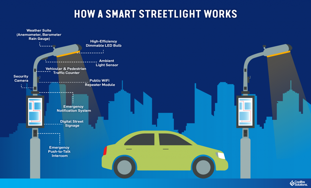
Today streetlights are viewed as an underutilized asset. In the coming years, street lighting poles will be seen as more than fixtures for luminaires, but as outlets for electrical energy and be used for other purposes such as charging electric vehicles, operating WLAN routers and video cameras, as well as hosting sensors. Which is the application space for the LUMAWISE Endurance S connectivity platform. Providing manufacturers with a standard mechanical base to build electronics on to, coupled with a new DALI based architecture this new technology allows for an endless list of connected sensors to be developed. Already entering the market are the more traditional sensors such as photocells and central management systems. This is shortly followed by motion detection, but why stop there? Exchangeable modules could be developed for traffic counting, incident detection, pollution monitoring and for identifying free or occupied parking spaces.

Move Towards Central Management Systems
With an increased use of LED in outdoor applications, local authorities, councils and utility companies will have already reduced their energy consumption. To realize further savings comes a growing need for control of the LED. As a consequence, many luminaire operators are considering moving from streetlights with basic functionalities (photocells) to more flexible Central Management Systems (CMS) that offer more control, better programming, and higher efficiencies. However, this decision to move to a CMS does not need to be made on day one. As LUMAWISE Endurance S modules is a pluggable system, a luminaire can be installed with a simple photocell or even with no control and later extra functionality can be added or replaced. Giving a streetlight a truly 20 years of useable life.

The LUMAWISE Endurance S modules consists of a standardized interface between the receptacle and module base or sealing cap. This uses an integrated single gasket that can accommodate and seal both luminaire and module using the same connection interface for either 40mm or 80mm diameter central management systems. This allows different modules to be exchanged and upgraded in only a few seconds, without having to electrically isolate the lighting pole.

Designed specifically for outdoor LED light sources and drivers, LUMAWISE Endurance S modules has been created as a standalone system and can be used in a complementary function as an auxiliary sensor module when additional functionality is required in ANSI/NEMA based fixtures.

Installation is easy thanks to its simple push-and-twist lock feature which does not require any tools and can be completed using one hand. The LUMAWISE Endurance S modules can be mounted in any direction and offers improved sealing when compared to other systems. Modules can be exchanged and upgraded in only a few seconds without having to electrically isolate the lighting pole.

LUMAWISE Endurance S modules was developed with several partners to ensure a complete system is available, including application specific drivers and control nodes. The partners also collaborated with the Zhaga Consortium. This is a global lighting-industry organization that is standardising components of LED luminaires, including LED light engines, LED modules, LED arrays, holders, and electronic control gear (LED drivers) and connectivity fit systems. Having these standardized components helps to simplify LED luminaire design and manufacturing, and to accelerate the adoption of LED lighting solutions.

Zhaga describes a connectivity fit system for smart outdoor luminaires in what is called Book 18. This is Zhaga’s most recent contribution to the rapidly-emerging world of smart lighting. Book 18 defines a standardized interface between an outdoor LED luminaire and a sensing/communication module that sits on the outside of the luminaire. The module connects to the LED driver and control system, and typically can provide sensory inputs while also communicating with other luminaires in a network.

The focus of developing this new Book 18 specification was to demonstrate the potential of new architecture and new functionalities which can create value for developers, installers and users of outdoor lighting. The standardized interface defined in Zhaga Book 18 enables the installation of future-proofed outdoor LED luminaires, which can be easily upgraded with smart communication and sensing capabilities. Zhaga member companies are already using the specification to develop products that will stimulate the market for smart outdoor LED luminaires.

The development process was relatively short: TE first started work on this in early 2016. Throughout the process, the product developers worked closely with the Zhaga Consortium, which is responsible for developing specifications that enable the interchangeability of LED light sources made by multiple different manufacturers. As a result, the new module now sets a new standard for European outdoor luminaires, providing an alternative or complementary solution to existing ANSI/NEMA product lines.

Categories Lighting

Flicker, Shimmer and Ripple – Lessons in Light Quality

Lighting oscillation characterized by flickering and sometimes shimmering between on and off is universally a bad experience – to consumers, lights should be either on or off. The human eye easily detects low-frequency oscillation in output light amplitude (intensity). Therefore, lighting designers must attempt to minimize any periodic disturbances below 2x the line frequency (< 100 Hz) to avoid unacceptable (detectable) variations in light output.  

There is some confusion in the market over terms used to describe variations in light intensity, possibly not an entirely accidental state of affairs, so let’s look at what is acceptable and what is not.

Flicker is Not Acceptable – Flicker is a rapid light-dark oscillation of the light source at low frequency. In solid-state (LED) lighting, flicker is typically associated with the misfiring of a TRIAC dimmer when presented with a high-impedance LED driver (dimming will be described in another article). A consumer confronted with a flickering light source, will change that light source.

Shimmer is Sometimes Acceptable – Shimmer is a variation of the light output from a light source. It is also low frequency and varies between almost imperceptible and extremely obvious. Depending on the application and the proximity of other light sources, a certain amount of shimmer may be acceptable to the user.

Low Frequency Components Cause Shimmer and Flicker – All power supplies for solid-state lighting have a ripple component in the output current they deliver to drive the LEDs. Depending on the topology selected, this can be in the order of 1 percent to 100 percent (how ripple is measured will be described shortly). The frequency of the ripple typically comprises 120 Hz or 100 Hz (for 50 Hz AC line voltage regions) and a higher frequency component typically in the 30 kHz to 100 kHz region. It is worth noting that 100 percent ripple is not new in lighting. Low-pressure-sodium streetlights (the yellow ones) typically exhibit 100 percent output ripple as do several types of compact fluorescent tube lamps. Single-stage bulb drivers are by far the most widely used LED bulb drivers in the market today and typically have output ripple current in the order of 30 to 100 percent.


Figure 1. Typical output current and voltage waveforms for an LED driver

The Role of Frequency in Determining the Impact of Output Ripple – In describing flicker, shimmer and ripple, both amplitude and frequency were described. The frequency of the variation in light intensity is critical because the human eye is extremely sensitive to low frequency variations but quickly becomes insensitive to variations above 100 Hz. LED drivers are designed to eliminate very low frequency ripple, in the sub 100 Hz range. Asymmetric TRIAC operation in deep dimming is one example of a condition that can cause obvious shimmer when TRIAC dimming – it is readily noticeable because of its 50 or 60 Hz operating frequency.

100 Hz and 120 Hz ripple is not easily seen by most observers. Even so, various lighting standards and guidelines regulate output ripple in order to limit secondary (stroboscopic) effects and to further reduce the likelihood of noticeable shimmer. In addition, some LED manufacturers are reluctant to publish limits in the amplitude of the ripple current that their LEDs will tolerate. Very high ripple values can reduce the average current that an LED string can pass without exceeding maximum current limits – reducing the effectiveness of the LEDs and increasing cost.

How Ripple Current is Measured and Specified – While it is not a perfect match, the variation in light intensity provided by LEDs in a light source closely follows that of the current used to drive them.

LED-driver specifications typically describe the acceptable ripple as the ratio of peak-to-peak current as a percentage of the average current. Energy Star has opted to prescribe Flicker Index in its guidelines.  Flicker Index is the ratio of the light output above and below the average in one cycle. Japan also has a limit for output ripple (the Denki-Youhin-Anzenhou – Safety requirement for Electrical equipment) that requires the minimum output current to be more than 5 percent from maximum output current; frequency of ripple must be ≥100 Hz. Japanese customers often opt for very low ripple current designs to meet the required specifications of local LED manufacturers.

How to Reduce Ripple Current – Increasing output capacitance will reduce ripple current but space is often limited and additional capacitance is expensive.  Another alternative is to use a linear regulator that can smooth out the peaks in the ripple current. While this is extremely effective, the linear regulator components do add a cost burden and reduce the driver efficiency by up to 6 percent (see Table 1). Figure 2 shows an Active Ripple Current Filter (ARF).


Table 1. Active Ripple Current Filter (ARF) efficiency


Figure 2. ARF diagram

Active ripple reduction circuits can also be used – the LED driver detects and compensates for the reduction in output current associated with the rectified AC line cycle. These circuits can reduce ripple by a small amount without the bulk of electrolytic capacitors, but they significantly reduce power factor.

Wonderful Technicolor – Once the designer has managed to keep the lights on without variations in intensity, they next have to focus on the quality of the illumination provided. Features such as color temperature have some regional variability (Northern climates tend to prefer cooler colors), and the Color Rendering Index (CRI) becomes important, especially when the lighting environment is to be used to view something. We will look at the meaning of terms including Color temperature, CRI and MacAdam ellipsis next month in the second half of this article.