Categories LED

LED High Bay Luminaires – Ready for Prime Time

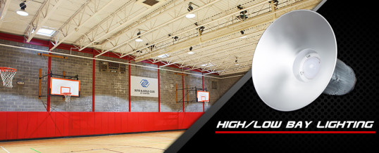
High bay lighting is the most common type of lighting used in commercial facilities that have high ceilings and require high foot-candle levels. They are ideally suited for warehouses, cold storage, airport concourses, grocery stores, gymnasiums, convention centers and other large indoor spaces with mounting heights between 15 and 40 feet, and ambient temperatures between -4°F and 131°F.  While high bay lights have traditionally used high intensity discharge (HID), metal halide (MH) or florescent lamps, many specifiers and facility managers are changing to LED luminaires. 

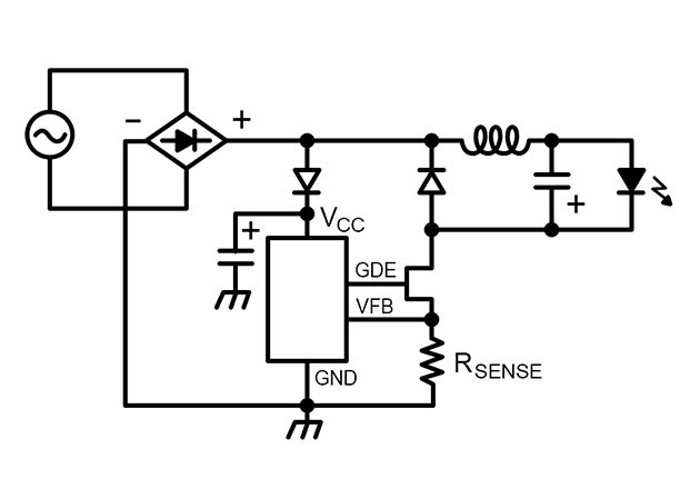
Properly designed and engineered LED-based high bay luminaires can offer big advantages for commercial applications. However, it’s important to consider LED luminaires that take a systems-level approach that includes driver design and thermal management, rather than just retrofitting LED “bulbs” into existing fixtures.  Thermal management is critically important to achieve the reliability expected from LED luminaires.  Extreme temperatures, both hot and cold, are common in high bay environments and can have a negative impact on the performance of electrical components.

Compelling LED Lamp Life 

  • 50,000 hours or better (5 years or more)
  • Minimizes the cumbersome maintenance of high ceiling applications

Advantages of LED Technology

  • Exceeding government mandated efficiency standards
  • Controlled distribution of light for enhanced uniformity
  • Higher luminaire efficacy

Let’s examine in more detail the many advantages of LED technology for high bay fixtures and a few application examples.

Warehouse Lighting
According to the Department of Energy, lighting uses as much as 29 percent of the electricity generated in the US and for industrial facilities, traditional lighting:

  • Uses 38 percent of the energy in a typical warehouse
  • Requires 15 percent of the energy in a refrigerated warehouse
  • Consumes 75 percent of a warehouse facility’s energy expenditures when maintenance is factored in with energy costs

Here’s where LED luminaires’ dramatic energy efficiency really makes an impact, particularly because many facilities that illuminate with high bays are in operation 18 to 24 hours a day. Typically, lighting is viewed as a fixed expense, but it shouldn’t be; energy costs can be dramatically reduced, up to 75 percent, and maintenance can be virtually eliminated through the installation of LED luminaires. Additionally, paired with occupancy sensors and/or dimmable components they provide even greater energy efficiency.

Further power savings are achieved from turning off the fixtures when not in use. Workers often leave the traditional lights on continuously because they take so long to warm up to full brightness. LED luminaires light immediately, eliminating the need to have them on all the time.

Many LED retrofit installations don’t require a one-to-one replacement so the combination of using fewer fixtures for shorter periods of time provides a lower energy bill and significantly reduced maintenance expense.

Cold Storage Lighting
With large, open spaces to cool, as well as sizable lighting requirements, cold storage facilities can consume vast amounts of energy.  As in any business, owners and managers of cold storage warehouses are often faced with minimizing their operating costs.  The energy used by the refrigeration system is often a major contributor to this cost of operation.

Conventional lighting and refrigeration systems typically work against each other.  Lighting systems generate heat, which the refrigeration system needs to remove.  In addition, lower temperatures typically reduce the efficacy of lighting systems.  Therefore, more power is required to generate the desired illumination, which in turn, increases the load on the refrigeration system.

Facilities can save tens of thousands of dollars in yearly electric costs, and cut harmful emissions by thousands of tons by implementing a handful of simple, cost-effective efficiency measures to reduce electrical consumption and have a payback period of three years or less such as installing LED luminaires. [1]

Only certain technologies, such as LED luminaires, are capable of functioning for cold storage needs at temperatures that range from zero degrees to -40°C.

Gymnasium Lighting
For years, the standard method of lighting gymnasiums has been the 400 W MH high bay.  This has led to gyms with deteriorating light levels and poor playing conditions that are expensive to operate. The MH system is essentially an “on-off” system that provides little control over light levels.  Also, these lights require 10 minutes or more before they reach their full light level.  After they are turned off, they require a similar amount of time before they can be turned back on again.  As a result, these lights are typically turned on in the morning and kept on until the building closes, regardless of whether there are any activities in the gym.  Additionally, MH use a lot of energy but produce less light as they age, giving gyms and other facilities poor illumination.

LED high bay luminaires deliver instant white light with no restrike or run-up delay.

LED Lamp Life
Correctly designed LED will not fail catastrophically, but rather slowly dim. LED luminaires are determined to have “failed” when light output reaches 70 percent of original output. In fact, well designed fixtures can last over 50,000 hours making non-scheduled equipment downtime due to lamp failure nonexistent.

How long is 50,000 hours?
Based on the length a fixture is illuminated per day, here is what a 50,000 lifetime translates into on an annual basis:

Hours of Operation –  50,000 hours is:
24 hours a day 5.7 years
18 hours per day 7.6 years
12 hours per day 11.4 years
8 hours per day           17.1 years

With LED luminaires, maintenance costs are minimized as relamping may not be required during usable lifetime of the product. Another important consideration given that high bays are ceiling-mounted and may need the use of a lift to change out the burned fixture.

LED Illumination – Ready for Prime Time
Debate continues about whether LEDs have the output in lumens. Through advancements in technology and manufacturing, bright white LED luminaires for commercial lighting applications are in the market. Recent legislation in the US has led to the phase-out of mercury vapor ballasts and lamps as well as 150 to 500 watt MH luminaires. LED technology fills these needs, while far exceeding government mandated efficiency standards.

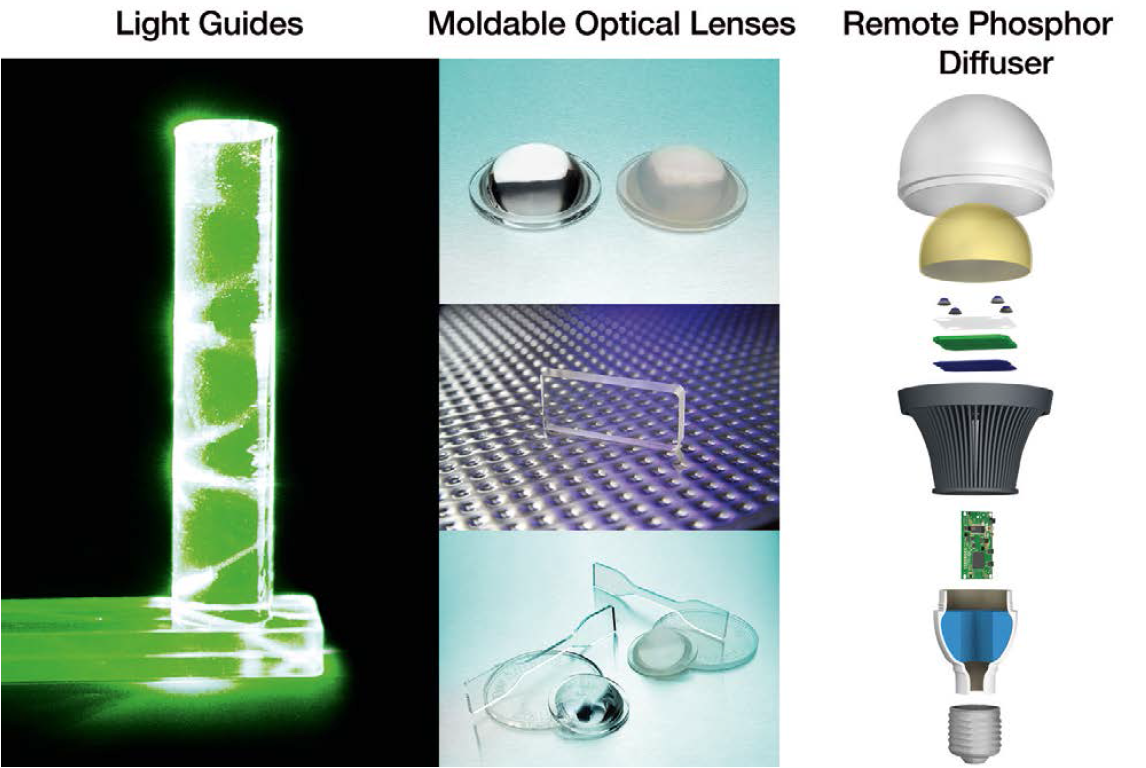
A LED luminaire incorporates an array of point sources that direct light precisely where it’s needed, with very little scattering or loss. Light distribution is controlled by the placement of LEDs, as well as by efficient use of optics that take advantage of the focal point presented by each individual LED.

Since traditional lamps are high-intensity near-point sources, the optical design for these luminaires causes the area directly below the luminaire to have a much higher illuminance than areas farther away from the luminaire. In contrast, the smaller, multiple point-source and directional characteristics of LEDs can allow better control of the distribution, with a resulting visible improvement in uniformity.

LED luminaires use different optics than traditional lamps because each LED is, in effect, an individual point source. Effective luminaire design exploiting the directional nature of LED light emission can translate to lower optical losses, and higher luminaire efficacy.

Categories Lighting

The March of Mid-Power LEDs into General Lighting

The research firm IHS just released a 2014 forecast for the LED general lighting market, which indicated that mid-power LEDs would represent >80 percent of the LED units shipped and roughly 48 percent of the revenue.  This is quite a change from a few years ago where revenue of high power LEDs dominated the general LED lighting market. There are numerous factors that have driven this shift including improved LED efficacy, adoption of lower cost plastic packaging, and a shift from magnetic transformers to mechanical approaches to achieve safety isolation.  This is especially true in integral bulbs and as a result the LED string voltage is no longer limited to 30 to 60 V depending on the regional safety requirements.

In some cases mid-power LEDs are a combination of several low power LEDs in series in a single package.  As a result, high voltage mid-power low current LEDs are available with typical forward voltages ranging from 9 to 100 V. One impact of using these LEDs is that alternate driver topologies instead of the classical isolated flyback can be used that result in lower electronics cost and/or higher power conversion efficiency.


Figure 1. Single LED string direct AC drive operation

One of the simplest direct AC approaches involves a bridge rectifier, constant current regulator (CCR) and a string of LEDs as seen in Figure 1. If the LED string voltage is sufficiently high compared to the input AC voltage, the losses in the CCR can be kept to a reasonable level while achieving > 0.9 power factor.  This approach does have lower LED utilization since for a portion of the AC cycle, no current flows through the LEDs as seen by the red line.  In this example there is no electrolytic capacitor in the circuit for energy storage so this type of driver results in 100 percent optical flicker at 100 / 120 Hz (2x the AC line frequency) but the driver circuit is simple, small and can have a long operating life time.   As it is not always practical to match the LED string voltage to the AC line voltage a switching topology is needed.

To better understand how to determine the right switching topology based on the string voltage, we wanted to compare several mainstream topologies and provide some general guidelines to help designers understand how the selection of the LED string voltage impacted the topology choice.  To do this a figure of merit (FOM) was created that combined the maximum voltage stress and peak current through the power switch as a function of the LED forward voltage and the input line voltage.  This FOM is a good proxy for both efficiency and cost in a switching LED driver as the lower the peak current, the lower the losses in the switch, inductor and diodes.

Two general use scenarios were considered. First, applications where high power factor and low THD (<20 percent) were required and the second where high power factor is not required.  As an example for ENERGY STAR LED lamps, there is no power factor requirement for lamps < 5 W and in the EU there is a special input line harmonic exception in EN61000-3-2 for lighting products < 25 W so high power factor is not required.  An added benefit of not needing high power factor is that it is easy to achieve low optical flicker.

The buck, buck-boost, boost and isolated flyback with a turn’s ratio of 3 were all compared based on the FOM (the lower the better) as a function of the VF to Vin peak ratio.  In the case of the high power factor case, the total harmonic distortion was limited to < 20 percent for analysis and we assumed a 600 V MOSFET (80 percent derating).  For VF/Vin ratios from 20 to 40 percent, the power factor corrected buck is the best topology. The upper limitation of the buck is related to THD and power factor and not stress on the power switch.  Interestingly it turns out the best topology from the FOM analysis is the boost, which is not the first topology to come to mind for many designers.  An example of a complete high PF 10 W boost design is shown in this design note where a 220 V LED string was driven at 30 mA across an input voltage of 90 to 135 Vac.


Figure 2. Topology comparison for high power factor >0.9


Figure 3. Topology comparison for low power factor (EN61000-3-2 Class C Exception)


When looking at applications were it is not critical to achieve high power factor, the clear winner for strings of higher voltage LEDs is the buck topology as seen in Figure 3 as it has the best FOM across a wide range of forward voltages.  An added benefit of this approach is that it is one of the simplest to implement and can have low optical flicker. The reason that the curve ends below 70 percent is due to meeting the requirements of the EN61000-3-2 Class C exception where the input capacitor is undersized to control the input current shape. For applications in the US market where compliance to EN61000-3-2 Class C is not required, this range can be extended. An example of a complete 3.8W buck design is shown in this design note where a 150 V LED string was driven at 25 mA across an input voltage of 200 to 265 Vac and achieved 85 percent efficiency.

This FOM comparison is a good reference tool at the beginning of the LED selection and architecture definition.  In some cases, especially at more narrow VF/Vin, there are several options that should be considered since the differences between different topologies is relatively small but in many cases this can give clear guidance in what topology is best for lowest system cost and better efficiency.

Categories Blog

SSL-Specific Connectors, Why are they Different?

As lighting designers, you’ve probably faced the inevitable decision of what connectors to use in your latest fixture design. You go to a website or open up a catalog and you’re faced with a broad and sometimes dizzying array of connectors to choose from.  If you’re early enough in the design process, there’s typically a pretty broad range of connectors that you can consider for your application. On the other hand, if you’re a designer that waits to the end to select connectors, your options can be pretty limited due to board layout constraints and configuration of components.

A number of the connectors you’ll come across in a general search were, in all probability, developed for some other application in a completely different industry. Could you get them to work in your application? Yes, maybe. Would they be an ideal fit? Well, therein lies the potential problem.

Let’s say you need a wire to board connector with a header that sits on the edge of the PCB along with a mating direction parallel with the board. You pull up the TE website and after using our product selector to isolate desired performance characteristics, you find our TE Micro MATE-N-LOK. It is a small, compact 3 mm centerline product that’s been on the market for years. At first glance, it has the voltage and current capability you need and it looks like it would fit your application from a foot-print standpoint. You pull up the customer drawing on the first part number listed and notice two things: 1) The housing is black and, 2) the latch on the top of the connector is 8.7 mm above the board.  You quickly conclude this connector is less than ideal since the height will probably mask light coming off your PCB mounted LEDs and secondly, the black housing won’t reflect the light further adding to the light blocking. All is not lost. Interestingly, if you scroll down the screen a little further, you’ll come across a variant that was designed specifically for SSL applications. It features a side latch design that lowers the profile to 5.26 mm and is molded of a white polymer to enhance reflectivity.  I’m sure you’ll agree the latter is a much better fit for your SSL design.

This is just one example of SSL specific connectors that enhance usability, performance, and assembly. Another example can be found in TE Connectivity’s standard and mini hermaphroditic connectors that were designed from the start for SSL applications. Targeted towards LED strip lighting, their unique multi-axis mating design allows a user to remove a single segment out of a series of LED strips without disconnecting and unfastening the entire series.  Because it is designed to mate to itself, a single part number can therefore be used on both ends of an LED strip. Try that with a pin and socket connector originally designed for a personal computer application!

So to close this blog, if you’re working on an SSL design, why not look at SSL-specific connectors first and early in the design process? If you don’t see something that exactly fits your needs, don’t hesitate to ask.  If you see something that almost fits your needs, ask about it as well since we at TE Connectivity aim to provide an extraordinary customer experience and are quite open to discussing variations of existing products to meet your specific requirements.  If you’d like to learn more about SSL lighting connectivity solutions or discuss Intelligent Buildings, please contact me at plieffrig@te.com.

Categories Lighting

Collaborative Approach Addresses Next Generation LED Lighting Design Challenges


The accelerating transition to LED-based lighting is changing the dynamics of luminaire design. Traditional approaches in which components are evaluated separately to arrive at an optimal BOM are being replaced by more synergistic, system level thinking. Several trends are driving this evolution in system design, which is supported by greater collaboration between providers of LEDs and power electronics components.

The first trend is the emergence of many new competitors, concurrent with rapidly falling prices for LEDs. While LEDs historically represented a large portion of a fixtures’ cost, other electronic components – including driver, power stage ICs and LED protection devices – are becoming a more significant portion of the overall BOM. And of course, there is relentless pressure to reduce the total end product cost.

Another major trend affecting the industry is increased demand for energy efficiency. This is best addressed by a system level approach and not by focusing solely on component selection. To respond to the efficiency challenge, the on-going migration to digital control of driver ICs and power stages for LEDs provides fixture designers with much greater ability to optimize power conversion.

Lastly, as LED-based luminaires become pervasive across multiple segments and different lighting sub-applications, there is enormous pressure to simplify the design process. To best address the widest number of market opportunities, fixture designers need to shorten development cycles. This is addressed by the emergence of simple and easy-to-integrate LED and power modules that reduce the level of complexity in design of the lighting element.

The flexibility to drive LEDs at different drive currents and different configurations, thus forming luminaires in different shapes and sizes than possible with traditional light sources, provides an opportunity for disruptive innovation in lighting. Yet this flexibility poses unique challenges for driver design. Until some level of standardization takes hold, each individual design requires custom drivers. The relative immaturity of control schemes related to dimming and other feature requirements can make driver design overly complicated and expensive. The application itself poses several challenges, whether it is outdoor wall-washing lights, or indoor down-light solutions driven from AC mains or from a DC bus or power-supply.

With these concerns in mind Infineon developed .dp, a Digital Power 2.0 generation of digital and intelligent LED driver ICs used in combination with state-of-the art power stages. The internal structure of the controller is built around a programmable Digital Signal Processor core, combined with optimized power-management and protection peripherals (Figure 1).


Figure 1. High-level digital LED driver IC architecture

High level integration as well as programmability offers several advantages, beginning with flexibility. Designers can employ several different drivers at different drive currents, and take advantage of features such as support of 0-10V interfaces and DALI interface compatibility. The LED driver can handle AC mains variants as well as DC input voltages in several different topologies such as boost, buck, fly-back, etc. Designs can easily be adapted through firmware changes, supporting fast time-to-market for variants of an original design for product line or market segment extension. Diagnostics and command-and-control (e.g. read out sensors, NTS, etc.) are greatly improved due to the digital nature of the part. Advanced controls support time based correction to prevent lumen degradation of a fixture and temperature compensation during color mixing to obtain desired colors or tunable white light. Fixture designers can add customized control code to support unique features, with the added code protected from reverse engineering efforts by security features that prevent readout of memory content.

With continued evolution of designs and manufacturing advancements, LED components will continue to increase in efficacy and light output. Manufacturers such as Philips Lumileds continue to innovate in response to the dynamic demands of the market. The vast selection of options and the introduction of more and more application specific LED components offer luminaire manufacturers multiple opportunities for innovation in such areas as energy consumption, light output, and lifetime claims to name only a few.

Let’s take the example of LED-based downlight fixtures. In the recent past, downlights were mostly constructed with a serial string of high-power LEDs, which meant relatively high drive current at relatively low forward voltage. Some manufacturers evolved this design by adopting CoB (Chip on Board) solutions with various current/voltage configurations depending on the serial/parallel configuration of the particular product. Today it is possible to construct downlights using an array of mid- or even low-power LEDs, introducing yet another long list of configurations and options. In all cases, the traditional design approach for these solutions quite likely involved re-design of the LED driver. This introduces cost and time-to-market complexity in terms of establishing design reliability, and conforming to fire and safety regulations around the globe. This complexity is eliminated with newly available, second generation digital power and power stage devices. Reconfiguration now is managed by simply re-programming the DSP based system to provide optimal efficiency at many Vf/If configurations.

Another example would be a luminaire manufacturer’s effort to expand across market segments, say from residential to professional and even industrial applications. While system geometries may be similar, retail price, light output performance or warranty requirements may be different. To address each segment successfully, it is desirable to minimize the number of fixed system sub-components and have the ability to simply change operating parameters. Taking the previous example of the downlight, let’s compare a residential with a professional solution. The usage profile in a private residence is completely different compared to a hotel hallway. The residential user is mostly interested in the initial cost to purchase whereas the hotel manager focuses on total cost of ownership. In this scenario the luminaire manufacturer may choose two different light engines – one low cost, the other high efficacy and high reliability – which usually require different driver configurations as well. With a programmable base product, the same driver subsystem with the appropriate firmware can be deployed to satisfy both scenarios with minimal design and qualification effort.

Yet another value of DSP-based programmable LED driver sub-systems is end of line calibration. Consider a luminaire that is exchangeable with its own kind, but due to uniformity reasons can’t differ from others in light output over its expected lifetime. In retail store lighting, where merchandise is illuminated by highly specialized lamps and luminaires, it is essential that newly added or replaced light sources have the same visual output as those already installed. There are two factors to consider in this case. First is the light output degradation over time. This can be compensated for by ever so slowly increasing the drive current based on either a pre-programmed or default current compensation curve, or by custom compensation patterns based on specific applications or needs. Secondly, as LED components keep improving in efficacy later versions of the same luminaire may require less current to achieve the same light output. At the same time lower currents mean lower stress and aging which in turn will have an impact on the long term lumen output stability – hence the light output compensation algorithm may need to be slightly adjusted as well.

In conclusion, market trends and the wider adoption of LEDs pose new challenges and open the doors to new market opportunities in the lighting industry. The trends include increased pressure to reduce system costs, the continuous increase in demand for energy efficiency and growing complexity of system design. To address these needs, the industry requires solutions to drive the LEDs that are flexible and that enable modular designs. The flexibility enabled by parameter setting or firmware changes can be leveraged at different stages of the product development or at different stages of production flow. Advanced controls such as time based correction, temperature compensation or end of line calibration can be implemented either through predetermined characteristics curves of LEDs or by sensing relevant parameters at the application level. Lighting designers should look to both LED and driver-IC manufacturers for components and modules that support a system level approach. This will allow them to take advantage of the full potential for innovation that LEDs bring to lighting at different levels of the supply chain and ultimately in the hands of the final customer.

Categories Product

The New Look of Flexible Touch Products – What's Coming

A wave of innovation in personal electronics is breaking. What’s helping drive these changes are several factors including incredibly small, highly integrated and far easier to program microcontrollers and flexible displays and touchscreens combined with silver nanowire-based technology, which no longer has to be flat. Rigid and flat are out. Flexibility is in. Such displays are here and being applied to products that will make today’s tablet computers appear as dated as desktops and push portable computing into entirely new sectors.

It’s no secret that wearable electronics are an exploding consumer category. Designers once struggled to make hard, flat products like notebooks and tablets survive frequent use. But now wearable products are an entirely new game. The good news is that touchscreen flexibility, a rather desirable feature for things attached to humans, is being significantly enabled by a leap forward in materials for touch-enabled products.

Flexibility = Wearability
In addition to providing enhanced portability, flexible electronics and touch interfaces also provide greater survivability and allow virtually unlimited design creativity. Flexible touch displays help enable flexible ergonomics, which can better withstand the harsh portable environment. Imagine unbreakable phone screens that flex instead of shattering when dropped. Consider a folding or roll-up a seven-inch tablet that slips into your pocket. How about a display that wraps around your arm, or even a huge public display wrapping around a pillar or a building like neon lighting does? We are driving toward products like these and they’re creating increasing demand for flexible, bendable and even rollable touch screens.

Some of these possibilities include but aren’t limited to curved-shaped smartphones, flexible tablets, as well as wearable smart bracelets and watches. Such products are particularly enabled by flexible touchscreen interfaces. Most importantly there is zero-downside in moving to flexible touch interfaces using silver nanowires versus rigid ones based on indium tin oxide (ITO), the traditional conductive material in flat touchscreens.

More Innovation, Lower Cost
Overall, silver nanowire-based touchscreens range from slightly less to significantly lower cost than equivalent ITO film-based solutions. The manufacturing/patterning processes don’t use chemicals; there aren’t waste disposal problems so it’s a greener way of making new touchscreens. Specifying silver nanowire-based touch technology doesn’t have a downside. Overall, its costs range from slightly less to significantly less than the cost of equivalent ITO, film-based solutions. Its advantages are numerous. The material is cost-effectively accelerating the transition to flexible and wearable devices and products we used to only imagine.

Enhancing the User Experience
As expectations for low-cost, high-performance products grow, so does demand for higher quality touch screens. Meeting today’s advanced standards means touch screens must be thin, light, visible in various ambient light conditions, highly responsive and of course low-cost. Fast responding transparent touchscreens are essential to the desired user experience. This result can only be achieved with highly transparent conductors not visible to the eye. An essential enabler of these important benefits is silver nanowire conductor technology.

For emerging touchscreen applications, including large-area touchscreens, as well as miniature, flexible wearable displays, silver nanowires offer a significant advantage, both in cost and performance. The material is already being used in several consumer products. Roll-to-roll processed silver nanowire transparent conductors are the clear choice for new production facilities needing high throughput and easy processing. They’re also on target for CE OEMs needing a thin, light, flexible material delivering high performance for their next killer product.

And for designers looking for creative possibilities, ask your suppliers about single-layer touchscreens and the higher conductivity, lower power consuming, silver nanowire-based solutions that are ready for wearable, flexible devices.

Categories Lighting

Evolution of Flexibility in Lighting

In the early years of solid-state lighting, manufacturers focused on ensuring LED luminaires and sources were first and foremost good illuminators. Manufacturers focused on efficacy, reliability, color and luminance. These early LED solutions were designed to behave and look like the traditional products they were replacing. As LED lighting matures, the focus is shifting toward designs that leverage the extraordinary flexibility of the LED. 

LEDs are semiconductor light sources that can be controlled like any other electronic components. The ability to control the LEDs, coupled with their inherently small size, opens the door to endless flexibility in lighting designs and features. For example, the lighting industry has seen an abundance of products with new dimensions of control such as intensity and color tuning.

While important, changing the hue and color temperature of lighting are not the only desired features to control. A critical dimension of light output control is the spatial distribution. Where the lighting is aimed, the beam shape, angles, and distribution are critical parameters.

What architects and designers really want is the ability to put bright white light exactly where they want it to create a perfect design. What owners really want is the flexibility to easily change that distribution as space needs change.

In multifunctional and reconfigurable spaces—such as retail shops, entertainment, hospitality, meeting rooms, museums, galleries and residential spaces—focal points and tasks can change frequently, so flexibility in the light distribution is valuable. A growing number of spaces are joining this category, such as modern classrooms and offices.

Even with the most advanced LED solutions, it was relatively difficult to change the pattern of light. For example, in a retail shop a typical solution is to use track lighting to complement the general lighting. This requires the addition of an accent lighting layer with appropriate luminaires. Each time the space changes, the track lighting must be re-aimed. The typical approach is to do this on a ladder, though some manufacturers offer motorized luminaires. This is labor intensive and expensive.

Using aimable lighting, we can direct the light where we want it, but the beam angle is fixed. Since objects and tasks not only change in terms of location but size and shape, the ability to adjust the light pattern becomes important. The industry responded with adjustable optics. This allows designers and owners to adjust the beam spread within a defined range, again using a ladder to individually access each luminaire

OSRAM SYLVANIA talked to designers, architects, retailers and specifiers about the flexibility they need to easily control lighting.  We attempted to address these different needs in a single LED innovation.

This new luminaire is extremely flexible.  Light intensity, beam shape and angle can be simply and easily controlled remotely using a wireless Android app.  The app allows the user to take a picture of the space using a wireless camera and then touch the image on the screen to aim light. Lighting conditions can be tuned and transformed instantaneously without the use of a ladder.

The recessed luminaire, called OmniPoint, consists of an array of LEDs that are focused through an aperture about the size of a five-inch downlight. Each LED is individually controllable enabling a virtually unlimited number of light patterns. The luminaire can provide ambient and accent lighting at the same time, which can be directed almost anywhere in the space in real time.  This flexibility may reduce the overall number of luminaires that are needed in the space resulting in a clean ceiling look.

This LED innovation is the result of natural evolution marrying new technology with longstanding professional lighting needs. At the recent LIGHTFAIR International 2015, it was recognized with an Innovation Award for the Most Innovative Product of the Year and also won the Innovation Award in the Recessed Downlights category. You can see it in action here.

Smart, connected LED lighting solutions that allow us to easily adjust parameters such as intensity, color temperature, hue, beam shape, angle, and distribution are rapidly emerging. These solutions are redefining how we think about, design, specify and use lighting everywhere.

Categories Lighting

Increasing LED Lighting Applications with Heatable Glass Lenses

In my last article, I reviewed examples and case studies on how glass (as luminaire lens material) can be successfully employed in various LED lighting applications to both optimize lighting efficiency and economic paybacks (ROI, TCO, etc.) in standard operating environments (i.e., temperatures > 32°F and 0°C).  In this article, the final entry in this series, I’m going to discuss ways in which a fabricated conductive/heatable glass lens can enable LED lighting to be effectively used in extreme environmental conditions that, to this point, have represented a hurdle towards wider market adoption.

LEDs offer high levels of flexibility and customization (output levels, color temperature, etc.) for lighting applications and, as such, have been and will continue to be adopted in almost every lighting market segment (as shown in the following diagram from the McKinsey Global Lighting Report of 2012).


As you can see, most areas in lighting are quickly migrating towards LED technology.  However, three segments seem to be lagging slightly behind:  Office, industrial and outdoor.  For office lighting, this can be rationalized by the still highly competitive position (in price and energy efficiency) of fluorescent (linear and compact) technology for this market.  For industrial and outdoor, though, there is a different roadblock stagnating LED adoption and that is simply the environmental conditions where these lighting applications operate.  In industrial and outdoor lighting applications, luminaires are seeing extreme weather conditions ranging from extreme hot to extreme cold (i.e., temperatures < 32°F and 0°C) with rain, snow, ice and hail exposure. These conditions, as you will see, prove to be an inherent problem for LED-based lighting.

In traditional outdoor lighting technology like Incandescent and  High-Intensity Discharge (HID) high levels of Infrared (IR) energy (see spectrum below) or “heat” are generated by the light source itself.


Diagram courtesy of Guardian Industries

With this IR heat comes higher energy consumption and lower levels of efficiency/efficacy, which has allowed LEDs to become a more-attractive technology long-term.  However, the absence of this IR heat generation from LED lighting vs. Incandescent and HID technology (as shown in the following output spectra) makes it difficult to use LEDs in lighting applications where it is necessary to remove snow and ice from the lens surface – such as outdoor and industrial.


Diagram courtesy of Guardian Industries Corp.

As you can see, the LED output is highest in the visible range and low in the Ultraviolet (UV) and Infrared (IR) ranges of the spectrum.  This means great visible light quality and low levels of UV damage and heat being generated which is good in terms of safety and efficiency.  However, this is bad news when you need that IR energy to remove snow and ice from your luminaire, which is “built into” HID light sources.  This issue has limited the market space potential for LED lighting in outdoor and industrial lighting applications.

LED luminaire OEMs have a number of ways to resolve this problem including:

  • Redirect heat from the heat sink into a cavity in the area between the light source and lens;
  • Integrated a conductive laminate interlayer (tungsten “wiggle wire”) on the lens;
  • Integrate a conductive coating on to the lens surface itself.

Let’s now assess each of these options. The redirection of the heat from the heat sink into the optical cavity is an easy fix but compromises the lifetime of the LEDs junction (one of its major commercial advantages).  Integrating a laminated conductive interlayer is another easy fix but increases luminaire cost and weight and compromises optical integrity and clarity.  Putting the heat directly where it needs to go, on the lens, clearly makes the most sense for LED lighting applications.

Now the question is on the lens material itself to use to accomplish this.

  • Plastics (PMMA Acrylic, Polycarbonate, etc.) are commonly used in LED luminaires but have limited ability to conduct heat or survive long-time exposure to it without degradation.
  • Glass is a proven material in this regard with its ability to be thermally stable > 1,100 °F and 600 °C.

By using a Transparent Conductive Oxide (TCO) coating on glass, we can provide a highly transparent yet conductive (15 – 20 ? /square) lens surface to create heat but still maintain high levels of optical efficiency (> 85 percent) with long-term thermal stability (because the coating itself has seen stable > 1,100°F and > 600°C in the tempering process).  The electrical interconnection can then be easily made through silk-screening buss bars with a conductive paint (such as Ag) onto the surface which are fired into the TCO coating during the tempering process.  By adding an Anti-Reflective (AR) coating, which has been covered in my earlier articles, you can raise the efficiency to > 90 percent.  The following diagram shows the configuration of such a fabricated monolithic heatable glass lens component.


Diagram courtesy of Guardian Industries Corp.

This monolithic heatable glass configuration would provide the following optical performance vs. traditional TCO technologies (Pyrolitic Fluorine Doped Tin Oxide) allowing for > 90 percent optical efficiency in the visible to be met with a single monolithic 5 mm glass lens while providing a conductive surface to heat the glass up to > 200°F (100°C) in temperatures down to -67°F (-55°C).


Diagram courtesy of Guardian Industries

In terms of heating the glass with this TCO coating, the following parameters and options are available for consideration and customizable during the luminaire design stage:

  • Input Power/Supply Voltage up to 100 V AC/DC
  • Operating Power Density range of 0.1 to 9 W/in² which, in consideration, with the following other attributes will determine the maximum surface temperature and heating ramp rate:
    • Input Power/Supply Voltage
    • Surface Area and Shape (rectangle, square, circle, etc.)
    • Terminals (Buss Bar) Size and Distance/Location
  • Electrical and Mechanical Interconnects
    • Terminal/Wires
    • Toggle Pins
  • Manual or Automatic Heating
    • Manual:  Simple ON/OFF control
    • Automatic: Thermocoupler with Feedback Loop

Last, because this heatable glass lens is tempered glass, it enjoys all the historical benefits associated with glass lenses that I mentioned in my first article including mechanical durability, chemical durability, environmental durability, and strength/impact resistance while providing the heating function.

In summary, we can form the following key takeaways about the use of a heatable glass lens to optimize optical efficiency for LED lighting in applications in extreme cold environments:

  • It further opens up the available market space for LED lighting into segments like Industrial and Outdoor where extreme environments requiring the melting of snow and ice prevented implementation and adoption;
  • It allows heat, to be focused on the lens area itself which reduces the risk to the lifetime of the LED light source itself;
  • It can heat the lens and, with the addition of an AR coating, can still reach > 90 percent optical efficiency; and
  • It offers a high-level of design flexibility and customization in terms of performance (optical and heating temperature and ramp rate) as well and serviceability (mechanical and electrical interconnections).

This is my final installment for the series on using glass in LED lighting and I’m confident that you will now look at glass in lighting a bit differently now than before. I hope that you will consider using glass as a lens material in LED lighting applications where you need to increase performance and differentiate your luminaires for competitive advantage.

Categories Lighting

Better Materials for OLED Lighting

LEDs have been replacing traditional lighting at a rapid pace, offering longer life times, more efficiency, lower cost, etc. OLED lighting promises to complement LED lighting by offering better color performance, power efficiency, unique shapes and designs, as well as a thin, lower weight and elegant profile. To enable OLED technology in this emerging lighting market, there is a need to replace traditional materials with new, better-performing materials such as silver nanowires.


Figure 1. Image of Silver Nanowires at 70° tilt

Silver Nanowires
In an OLED device, the top electrode is made of a transparent conductor and plays an important role in light transmission/efficiency. A transparent conductor made of silver nanowires allows for high conductivity with excellent transmission and acts as the top electrode/anode in the case of an OLED lighting system. Silver nanowires in the top electrode are used in the form of a network of wires (see Figure 1) that are a few nanometers thick and a few micrometers in length. With silver being the best conductor on the planet, the network of overlapping nanowires offers conductivity less than 10 ohms/sq while allowing 94 percent of the light to go through the percolated network.


Figure 2. High transmission of silver nanowires at low resistance (Photo courtesy – ClearOhm silver nanowire material by Cambrios Technologies)

Aesthetic Lighting
OLED lighting is not a point source and, therefore, does not need to be diffused or set at a distance from the area that needs to be lit. OLEDs emit light all through their surface and can be used to create aesthetically pleasing lighting structures of various forms and sizes. Imagine an elegantly shaped lampshade emitting light instead of the shade diffusing the light from the lamp within. Lights in any form factor that needs to be bent, curved or flexed, needs flexible transparent conductors. This can be achieved easily through the use of silver nanowires rather than thick and brittle conductors.


Figure 3. OLED lighting tiles. Photo courtesy – Panasonic

OLED devices can serve a dual purpose of being a window or a light. They can be made transparent – a window that you can see thru during the day and that would emit light at night. The skylights and car sunroof could not only allow ambient light to enter, also could become lamps at night. In such applications, it is important to have very transparent layers of OLED materials, another area where silver nanowire networks play a huge role.

In addition, OLED lighting can offer shades of color previously not possible with conventional lighting. Better color tuning is possible with silver nanowires, and OLED lights can offer a more precise shade of color for premium lighting applications.

2.5D Lighting
OLED lights can be produced on plastic substrates and coated with silver nanowires. These types of flexible and rugged form factors can be deployed on non-flat surfaces, such as the dashboard of a car. This type of 2D and 2.5D lighting systems are very desirable in high-end consumer devices, retail stores and museums where any surface can provide changeable color. The traditional transparent conductor materials like ITO (indium tin oxide) are brittle and don’t lend themselves to bending or shaping, hence newer materials such as silver nanowires, which are malleable and ductile, are preferred.

Thinner, Lightweight, Rugged
Silver nanowires complement OLED in that both materials are thin, lightweight and very rugged. The thin and lightweight features make them suitable for applications such as aircraft lighting and illuminating skyscrapers, and the rugged nature of the system (both OLED and silver nanowires can be coated on plastic or thin glass) makes them suitable for outdoor public venues, which typically require lighting that is not only bright but also unbreakable.

Conclusion
LED and OLED technologies will reshape the lighting market with more efficient devices that require less power and offer flexibility in design at lower overall cost. While LED technology is way ahead in replacing conventional lighting technologies, OLED lights will follow and offer lighting solutions that we have never had before. Silver nanowire technology has begun to enable these emerging applications.

Categories Blog

Enabling SSL Adoption Through Intuitive Interconnect – Part II

Last month we discussed interconnect of the Chip on Board LED device within a luminaire utilizing a TE Connectivity (TE) scalable or Zhaga compliant socket.  This month we’ll move another layer away from the light source and look at the various device-level interconnects commonly used in lighting applications. Lighting interconnects span a broad range of options from board-to-board, wire-to-board, surface mounted and inverted through board technologies.  The multitude of interconnect options for the fixture designer can be confusing, so let’s spend the time speaking about the attributes and merits of common interconnect classifications used in lighting systems.

Board-to-board applications: This connector technology allows the direct connection of two printed circuit boards. In lighting applications, this is usually in an end-to-end fashion. While a number of board to board options exist, a specific example shown is TE’s Hermaphroditic connector. This connector allows for end to end mating of board assemblies and also allows for horizontal and vertical axis mating enabling 90° and 180° articulation.  Linear, multi-segment, solid state lighting (SSL) board assemblies commonly used in cove lighting or linear lighting fixtures are ideal applications for this type of interconnect.

Wire-to-board applications: This category of interconnection can be further segmented into sub categories; two-piece separable, one-piece removable and one piece permanent. All accomplish the same fundamental task of bringing a wire to a printed circuit board in a simple, solderless approach. An example of a separable wire to board connector can be seen in TE’s low profile, micro MATE-N-LOK connector shown in the image at the right. A one piece removable solution is best illustrated by TE Connectivity’s innovative line of poke-in connectors that includes the micro poke-in wire SSL connector. Lastly, a one piece permanent connection between a wire and board can be accomplished with an insulation displacement connector such as TE’s SMT IDC connector. Termination with an IDC connector is as simple as inserting the un-stripped wire and pressing the stuffer cap down. The common thread shared by all these wire to board connectors is they are all low-profile wire to printed circuit board connectors designed specifically  for LED lighting systems whether they be channel lettering lighting strips, general illumination LED fixtures, architectural cove and valence lighting,  or LED modules for other applications.

There is another unique wire to board product that is worth noting here as well. The inverted through-board style of connector products provide an unobtrusive interconnect to printed circuit boards. By rotating the mating axis to mate from the underside of a PCB, connector exposure and wire routing issues on the LED side of the board are minimized.  The result is a clean, minimally obstructed light emitting surface ideal for use with LED array implementations in downlight, spotlight and even street-lighting applications.

To close, the interconnection is often one of the last items to be considered in a lighting design. The wrong selection can have long term ramifications in manufacturing, reliability and field repair. With a little forethought and understanding of interconnect options, design, assembly and repair can be optimized in lighting systems. Consider the following during your design efforts:

  • Is this a board to board application? If so, can this be accomplished with a direct board to board mating connector system or is a header/wire jumper assembly required by the application?
  • For wire to board applications is a separable wire to board interconnect required or can the wire be terminated with a one piece semi-permanent or permanent connector?
  • How many circuits need to be accommodated by the connector?
  • What is the end fixture application and what are the governing agency standards required by the fixture?
  • What is the voltage and current rating required?
  • What are the particular environmental constraints required (temperature, humidity, shock/vibration, ingress protection, etc.)?
  • Does your application require positive latching or is a friction latch acceptable?
Categories Blog

Which Driver Topology to Choose

Designing optimum LED drivers for Industrial, commercial and consumer applications requires a clear understanding of the application requirements. To achieve power factor correction, low total-harmonic-distortion (THD) and good output current control while meeting increasing cost and efficiency targets, only the most appropriate switching topology will suffice. Since there is no standardization in LED load voltage requirements, no single “best topology “exists. 

The aim of this month’s article is to explore off-line conversion and examine the factors that determine where buck, buck-boost, tapped-buck and flyback topologies are most effective.

Highest efficiency and lowest cost, input voltage range, output voltage range, THD, PF, regulatory requirements and the cost of isolated versus non-isolated topologies are all factors that need to be considered in selecting the appropriate driver.

Available Topologies
The simplest switching conversion approach is to use a buck converter – it has the lowest component count, a very simple (low cost) magnetic component (an inductor) and the highest efficiency.  The use of single stage combined PFC and CC controllers means that for PFC and low ATHD, buck converters are an attractive choice for non-isolated designs.


Figure 1. High-Side Buck Circuit using a Combined PFC and CC Output Integrated Control + Switching IC (Note that a high value aluminum electrolytic bulk capacitor is not required) [3]

Buck converters cannot provide functional isolation and requires the input voltage to be higher than the output voltage to work. The latter issue is important when considering THD. It can be shown that in order to meet EN61000-3-2 C/D standards for THD, the output voltage from a low-line input buck converter must be less than approximately 35 VDC. This limit is needed to keep the conduction angle (the proportion of the switching cycle over which the switching circuit is able to conduct and therefore influence input current wave-shape) high enough to effectively shape the input current to meet THD limits. For high-line applications, the maximum output voltage is approximately 70 to 75 V. In addition, Buck converters are not good at controlling voltage step-down if the ratio of input to output voltage is greater than approximately 8:1 due to duty cycle limitations in the controller.

Buck-Boost Converter
Buck-boost conversion is the next alternative – component count is similar to buck designs and efficiency is also very high. Buck-boost converters operate across a wider portion of the available conduction angle and so can provide good THD for higher output voltage designs. They have a similar problem with isolation and duty cycle limited input/output voltage ratio as buck converters.


Figure 2. Non-Isolated Buck-Boost Converter Employing Combined PFC and CC Single Stage Converter IC


Tapped-Buck Converters
The next category to consider as a possible solution is tapped-buck converters. The more complex winding structure of the magnetic element introduces a cost and efficiency penalty. However the transformer/inductor nature of the winding structure allows a turns-ratio type adjustment of output voltage and current, making tapped buck converters good for standard designs where the input to output ratio precludes the use of a buck or buck-boost topology. It is appropriate to consider the tapped buck converter as analogous to a non-isolated flyback converter


Figure 3. A low Power Tapped-Buck Converter (With no PFC stage)
Note the Wide-Input Voltage Range


Flyback Converters
The final category of LED driver we will consider is the flyback converter. The converter can be implemented as either isolated or non-isolated and the turns-ratio capability of the transformer allows for pretty much any ratio of input to output voltage. Due to imperfect coupling between primary and secondary windings, as well as primary parasitic capacitance, the more complex winding arrangement leads to increased cost and power losses. Flyback converters are overwhelmingly used for isolated LED bulb designs and use either a passive-valley fill PFC circuit (Valley fill is acceptable for 0.7 PF applications but induce 8 to 10 percent efficiency penalty in reaching the 0.9 PF required for commercial applications), or higher-efficiency combined CC and PFC converters that are available today.


Figure 4. High Efficiency Combined PFC and CC Converter in an Isolated Flyback Topology


Choosing the Right Topology
A summary of the decision process to select between different topologies is shown below. The selection strategy assumes the following order for designs: Buck →Buck Boost →Tapped Buck → Flyback. The order is weighted; highest efficiency and lowest cost being the most desirable requirements.


Figure 5. Topology Selection Flow Chart

Only if the best topology for each design is selected, can performance be guaranteed and the best design delivered. Every design will be different but all can follow the methodology described in this paper for deriving the most ideal solution for each application type.