Categories Blog

Realize Your Genius!

In recent blogs, I covered the LED; interconnect of the Chip on Board LED device within a luminaire utilizing a TE Connectivity (TE) scalable or Zhaga compliant holder; the various device-level interconnects; and control, circuit protection and power aspects of Solid State Lighting (SSL) luminaires.  Now, let’s bring it altogether for a visual illustration of an LED light source and how TE enables the proliferation of SSL applications. The LED itself is quite a demanding device and requires a number of components to achieve a luminaire.  These components form a community of interacting devices all linked together to make an LED ecosystem.  An ecosystem for an LED light source is illustrated below.

As lighting undergoes the transition to LED solutions, simplicity and compatibility between the devices of a SSL lighting system are fundamental to system performance and their ability to scale in manufacturing.  These building block devices include (from left to right in the illustration); heat sink, thermal interface material, LED, LED holder, optical interface, and secondary optic.  This forms the basis of the SSL ecosystem, which would include a driver and aesthetic packaging.

The holder (or socket) is the core for the electrical, thermal, mechanical and optical interconnection around the LED.  Design and simplicity of the interconnection is paramount, hence TE’s introduction of a vast array of SSL enabling products.  Emerging standardization and convergence of form factors, particularly in spot light and down light applications, is providing manufacturers the opportunity to employ platform based solutions.  The Zhaga consortium is providing significant influence in this standardization.

This ecosystem platform approach drives the reduction in customization of many key components within the SSL ecosystem, simplifying assembly, allowing a faster time to market with reduced investment for the luminaire manufacturers.  By providing a common interface to the LED, heat sink and secondary optics, TE is enabling this ecosystem to be broader reaching.  Products engineered to work together from the outset, creating solutions and addressing the reliability touch points, while bringing a mutual benefit for the luminaire manufacturer and the end customer. More details and video are available on www.te.com/ledholders

An ecosystem of engineered components offers greater supply chain flexibility.  With an assortment of interchangeable light LED sources and optics, OEMs can limit risk, avoid capital costs of customized components or subassemblies and perform late customization of products to respond faster to customers ever-changing needs.  Here TE’s distribution partners play a key role to provide the availability of many of the SSL ecosystem products– thus empowering customers to create their own LED modules with far greater ease and confidence.  In this respect, TE focused on aligning our product availability through the same distribution channels that provide the LED’s, optics, drivers and thermal materials.

The Intelligent Buildings division of TE Connectivity is enabling lighting applications far beyond the LED itself.  We are enabling the integration of LED’s in the luminaire via innovative socket solutions, optical interfaces and power connectivity.  We provide low power and high power DC distributions systems via our NECTOR power system and our affiliation with eMerge Alliance.  We enable communication of multiple device applications to building management systems via wired and wireless solutions.  We are bringing seamless integration of devices to unlock the full potential for lighting systems and solutions.  More details available here.

Categories Blog

Portable Generator Reviews: Best Portable Gas Generators

The Best Portable Generator for 2021 | Reviews by WirecutterPortable Generator Reviews: Best Portable Gas Generators

Three “Best” portable generators were selected for review on the ConsumerSearch (CS) website:

  1. Generac 5724.
  2. Honeywell HW2000i.
  3. Briggs & Stratton Elite 30242.

The ConsumerSearch (CS) website published mini reviews of each model, and provides links to longer CS “Our Analysis” reviews of the same portable generators.

ConsumerSearch claims “…at no point are our editors influenced by advertising or other commercial considerations.” The organization investigates and recommends a variety of products. The company, a service of About dot com, provides on-line product ratings and reviews, such as the “Best” wind power generators, “Best” car tires, and the “Best” lawn tractors.

Generac Generators: Model 5724 “Best” Portable Generator Review

The Generac 5724 (est. $450) has a Good Housekeeping Seal giving it an additional warranty for two years in addition to factory warranty coverage. The 5724 received the CS “Best” designation because “..it [is] a better bet than similar generators in this price and size class.” The model can run a refrigerator, lights, and a “couple” of lower wattage appliances during a power outage. The generator provides 3,250 watts with 3,750 surge watts.

The Northern Tool + Equipment website provides Generac 5724 owner reviews praising the model and giving it five out of five stars.

The CS “Our Analysis” longer review lists the “pros” for the 5724:

  • The model has a fuel gauge.
  • The 5724 will shutdown when low on oil.
  • The handle folds down.
  • The model has a wheel kit.
  • The 5724 comes with a Good Housekeeping Seal.
  • The Generac 5724 is CSA (Canadian Standards Association) certified.

The “Our Analysis” lists the “cons” for the 5724:

  • The model is not CARB (California Air Resource Board‘s stringent air-quality standards) compliant.
  • The model does not have a DC outlet.
  • The model makes more noise than “similarly sized generators.”

Honeywell Portable Generators with Inverter Technology

The Honeywell HW2000i (est. $500) uses inverter technology for keeping voltage from harming computers and TVs by controlling electric surges. It weighs 58 pounds, and is light enough for camping or tailgating. The model has an economy mode setting which reduces noise and saves fuel.

The HW2000i meets CARB standards, and comes with a two year warranty. Included in this model are two AC outlets and one DC outlet. If the consumer does not need to power electronics (TVs, computers, etc.), a non-inverter generator will deliver twice the power.

Briggs & Stratton Gas Generator Consumer Review

The Briggs & Stratton Elite 30242 (est. $1,000) is powerful enough to run appliances and lights up to a 2,000 sq. foot structure. The model can surge to 8,750 watts and is capable of starting heavy duty motors. The 30242 has an electric starter with four AC outlets, one 30 amp AC locking outlet, and a 30 amp extension cord with four outlets. The model weighs 200 pounds and comes with a two year warranty. A possible downside is the 30242 can burn seven gallons of gas in eight hours.

The ConsumerSearch mini reviews web page provides additional information about each of the three CS “Best” portable generators. The mini reviews page provides links to longer CS “Our Analysis” reviews of the same models, and provides additional links to outside sources reviewing the same portable generator models.


Categories Blog

Produce Your Own Hydrogen – The Homemade Hydrogen Generator

How to make a mini Hydrogen Generator / TUTORIAL - YouTube

There are many different designs of hydrogen generators available on the Internet. There’s also many schematics available to download showing exactly how to build your own hydrogen (or Brown’s Gas) generator. While adding this component to your vehicle, keep in mind that some vehicles may not benefit from the injection of Brown’s Gas but many will – especially in smaller, older vehicles.

Vehicle Compatibility for Brown’s Gas

Some vehicles, especially newer vehicles with all the computer controls, could possibly run erratically if you introduce Brown’s Gas into the air intake system. This is primarily due to all of the sensors that are installed on vehicles today.

When Brown’s Gas is introduced into the air intake system, it enriches the quality of the air by adding hydrogen and oxygen. Vehicle engine sensors are designed to detect “normal” air quality and make any adjustments to the engine necessary if air quality changes. When they detect the hydrogen and oxygen enriched air in the air/fuel system, the computer will automatically make changes to the air/fuel mixture and cause the engine to run erratically.

Some people have avoided this problem by removing the air sensors from the vehicle and replace them with a fake sensor that makes the computer think that the sensor is still there, but unlike the air sensor, the fake sensor does not send any signals to the vehicle computer. There are also other methods to avoid this problem and a quick Internet search on “vehicle sensors and Brown’s Gas” will show ways to avoid computer issues.

The Homemade Hydrogen Generator

The hydrogen generator that you build should be designed especially for the vehicle in which you are installing it. You need room for the hydrogen generator, and it should also be located close to the battery (for power).

Components List

You will need at least the following components to start building your hydrogen generator:

  • A canister large enough to contain the water, electrolysis plates, and wiring.
  • At least two stainless steel receptacle wall plates.
  • Grommets, plastic or rubber washers, and stainless steel screws.
  • Heavy duty wires (6 to 8 gauge) – red (positive) and black (negative).
  • Fuse boxes with at least 30 Amp fuses
  • Enough plastic tubing to connect the canister to the fuel intake system.
  • An on/off power switch to allow power to be controlled to the generator

Basic Instructions for Building a Hydrogen Generator

Many different types of containers can be used to build a hydrogen generator, but the most common is a standard 6” to 8” PVC pipe cut to the desired length. The pipe must be completely sealed to allow the gas to be contained and captured. PVC caps or threaded ends can be used for this.

The stainless steel wall plates are those used to cover an old receptacle that is no longer used. These can be found in any hardware store. Stainless steel must be used because it does not corrode as regular steel will. Electrolysis will corrode normal steel within minutes.

The steel wall plates should be sandwiched together but not touching. Mount the grommets inside the “screw holes” of the wall plates, use the rubber washers on the outside of the plates and attach them together with the stainless steel screws but leave each screw attaching a separate plate. The plates must not touch each other but each screw needs to touch each plate.

Connect the red (positive) wire to the screw on one of the plates, and connect the black (negative) wire to the opposite screw on the other plate. You should now have about a 1/8” space between the two plates with each wire connecting each plate. One plate serves as a positive conductor while the other plate will serve as the negative conductor. When powered, the current passes through the water within the canister – breaking down the water into its single atoms (hydrogen and oxygen).

A plastic tube (normally around ¾”) should be inserted through a drilled hole near the top of the canister where the gas will collect. It is this tube that will connect to your vehicles intake system; supplying the Brown’s Gas. As a safety precaution, connect the hose to the hydrogen generator canister and run it into a separate canister which contains water – then finally connect it to the intake system of your vehicle. This secondary canister will help prevent a disaster in case the gas is somehow ignited by the engine.

Install an on/off power switch on the inside of your vehicle – and connect to the red wire supplying power to the hydrogen generator. There’s several different ways to connect the power switch so do a bit of research on this. Also install the fuse box in-line with the power supply wire. If a wire was somehow shorted out, the fuse will blow instead of causing electrical damage or fire to your vehicle.

Connecting to the Air Intake System

Most vehicles are equipped with a rubber type, air-intake component which connects from the vehicles air filter directly to the engine intake. It is this rubber component where you will want to connect the tubing from the hydrogen generator. When the hydrogen generator is operating, pressure will build inside the container – which will force the gas into the engine’s combustion chambers.

More Information on Building These Systems

By no means can this short article describe all of the science involved in building a Homemade Hydrogen Generator. It was written to cover the very basics of this component and to give you a brief idea as to how they work and connect to a vehicle. I’ve included several links below that should be reviewed before attempting to build your own hydrogen generator.

And remember; take caution when building these because they can explode!

Categories Blog

Metrics – One Size Fits All?

LEDs are the answer. Now just tell me what the question is. That’s what it seems like, doesn’t it? Nobody doubts the promise of LED technology, and certainly the unprecedented design flexibility is very exciting. It seems, however, that anyone with any LED experience has a disappointing one among their forays.  So what’s the matter with all of us?

It’s become clear to me that some of these problems stem from familiar metrics and guidelines that are no longer sufficient.  We roll our eyes at naïve consumers who quantify their needs in terms of a “60 watt light bulb,” but perhaps it’s time we reconsider some of the other metrics that have been convenient, handy and “good enough.” For today, let’s pick on color quality.

For the most part, if it is important to have objects look attractive, we seek light sources with a color rendering index (CRI) in the 80s or higher.  Perfect, we reason, would be a CRI of 100.  We rely very heavily on that number, but will that really get us what we need?

The CRI scale was developed to measure color fidelity compared to a reference light source – at most color temperatures, an incandescent type source.  If we believe that incandescent light quality is the ultimate goal, then a CRI of 100 would represent perfection.  Those who have ever left the house with a navy blue sock on one foot and a black one on the other, however, may not agree with that assessment.  As guidelines for legislation and financial incentives are set, we should remember that CRI was never intended to indicate fitness for an application, nor does it say anything about preference by any population.

Averaging the appearance of eight pastel colors for what is reported as the CRI (Ra) metric is a compromise of convenience, but there are six additional reference indices that can hold more information.  But is higher always better?  Many highlight the R9 (deep red) index, since people generally want to look healthier and better rested than they may actually be, but does even that tell the whole story?  Many people prefer neodymium lamps in their homes, which transform standard incandescent lamps from 100 CRI and R9 of 100 to a CRI of 77 and an R9 of 15.  There are CFL lamps that are nearly indistinguishable from incandescent lamps at the same 82 CRI of their disdained cousins, but with an R9 value of 20 rather than zero (or lower).

It turns out that we don’t actually like to see all colors.  We tend to prefer red tones (ruddy complexion, toasty fireplaces).  We don’t like yellow so much (jaundice, sickly appearance).  So maybe we don’t actually want all indices to score 100?  This logic may be great for residential applications, but perhaps not for healthcare settings.  I would certainly want my pediatrician to readily recognize jaundice in my baby.

While there are new scales being developed, like the color quality scale (CQS) and gamut area index (GAI), the issue still remains – is our goal color fidelity (versus what as a reference) or preference (whose preference)?  The answer is likely “it depends on the application.”  As an example, the DOE’s Retailer Energy Alliance has recognized that in their performance specification for refrigerated display cases, where they include minimum values for saturated color indices R9 through R12.  So maybe the metrics are actually fine.  Maybe we need to remind ourselves what they actually were intended to measure, and consider identifying additional complementary metrics to define exactly what we are trying to characterize.

Categories Blog

Is Low Price Really Low Cost?

When building an LED luminaire or lamp, total price of components in the bill of materials is a critical to the commercial success and adoption of a product in the market.  Another factor that is truly important in the long run of manufacturing LED products is the total cost for such components and the ability to meet the expected lifetime demanded by the market.  The LED lighting market is demanding high reliability and long expected lifetimes of products in excess of 50,000 hours.  Total cost not only takes into account the price of components, but also the costs associated with issues such as manufacturing quality, warranty claims, and brand reputation due to reliability issues.

The industry has already started to see some of these associated costs in instances related to failures of electrolytic capacitors in drivers and optical performance degradation due to lens material complexities in LED systems.  Connectivity products for LED systems are also important components that are not immune to such concerns and need to be carefully evaluated for quality and reliability when selected during the design process.  While the price is important, selecting the right connectivity solution may prove to be less expensive to a manufacturer over time.

Understanding the basics of the connector design and test process helps a fixture designer make a confident component selection to meet market demands.  The basic connector consists of a housing and contacts used to create the electromechanical interface. The interface can be used for wire?to?wire, board?to?board, and wire?to-device/board connections. The purpose of the connector is to establish and maintain a reliable, yet separable low?resistance connection. The contacts used in a connector system are at the heart of what makes a connector work.  Correct material selection is critical to ensure adequate normal force is retained at the interface during the life of the connector.  The connector housing provides a number of very important functions. Fundamentally, the housing provides electrical isolation between adjacent contacts and between the contact and the outside world.

In high?intensity LED applications, the LEDs themselves generate enough heat to require careful consideration of thermal management and material selections. Choosing the right connector is critical to ensure it meets the intended application and environmental conditions just as with the LED, optics, thermal management and driver electronics.

Connectivity solutions should to be designed or evaluated for LED environments to minimize common failure modes such as fretting corrosion of contacts and other issues due to the effects of plastic relaxation that lead to catastrophic failures.  At TE Connectivity, we have developed design processes and testing procedures along with robust material selection guidelines to design high quality connector performance and field reliability.  Years of innovation and experience is embedded in TE’s design and manufacturing practices providing the market with the confidence it needs to build products with high demands for useful life at competitive prices.

In today’s solid?state lighting systems, LEDs, thermal solution, optics and packaging comprise a considerable part of the overall cost of the lighting system. The connector is usually a small part of the overall cost and is often specified without adequate consideration and balancing of cost versus performance. It makes little sense to scrimp on the one component that your entire fixture relies on for power. Without a reliable and appropriate connector system, the lighting fixture, however well designed and esthetically pleasing it is, becomes a dull, static (and unlit) non?functional object d’art. Spend some time and consideration selecting the appropriate proven connector system for the application even if it costs a little more. It will pay dividends in the long run.

The bitterness of poor quality lasts much longer than the sweetness of the lowest price.

Categories Blog

An Evolutionary Overview of SSL Connectors

Connectors for SSL applications continue to evolve as engineers push manufacturers for more unique and innovative solutions specifically designed to suit emerging lighting designs. Looking back over the past five years, one can see just how far SSL connector technology has progressed since the first solid-state lights started to appear in the market.

Early SSL engineers were limited to finding an existing connector that looked similar to what he needed and then drilling down to identify those that met performance requirements. Since connectors had yet to be specifically designed for SSL applications, however, the selection was extremely limited. Typically, if a connector met the high current or voltage requirements, it was too big for the design; and, similarly, if a connector was small enough, it was often not surface mountable (SMT) or robust enough. In fact, even finding a white connector was nearly impossible.

In the years since, we have moved past that “mission impossible” era. Now, there are multiple solutions available for most board-to-board (BTB) or wire-to-board (WTB) applications that emerge. However, these often appear as niche or individual product offerings with a limited range of options; so, engineers frequently still need to mix-and-match connectors from different vendors to meet the pin count or configuration requirements of SSL designs.

Based on a highly reliable gold-plated, beryllium copper contact system designed to match the 20+ year life spans of SSL products, the 9159 series of two-piece connectors from AVX Interconnect stands out as one of the few exceptions to this rule. The first connector in this series – the 9159 horizontal plug and socket (pictured in Figure 1) – was designed in response to a customer’s request for a coplanar, two-position, SMT, white, connector system that was 50 percent smaller than what was currently available on the market and capable of handling between four and five amps of current. Once that was achieved, the series was extended to include connectors featuring two to six positions to accommodate additional power or mixed power and signal lines and a greater breadth of SSL designs.


Figure 1. AVX’s 9159 series two-piece, coplanar BTB connectors

Over the next couple of years, as customer requests kept rolling in, connector engineers grew more accustomed to accommodating SSL-specific design requirements, and the initial 9159 products began to accumulate years of proven performance, the series continued to expand. First, a straight-cabled plug with an integral latching mechanism that maintains the connection integrity during handling and installation was developed in response to a request for a WTB solution that allowed engineers to build a common board layout with a plug on one end and a socket on the other. Capable of serving either a WTB or BTB function, this plug and socket connector enabled the development of a single board capable of achieving volume economies with almost unlimited expansion based on the required light output.


Figure 2. AVX’s current 9159 Series product offering

Next, a top load socket was developed in response to several customer complaints about board level failures in linear strings, which required technicians to disassemble the light out in the field until the defective board was reached. This solution features a slide-top design that acts a zero insertion force (ZIF) connector and allows one end of an interior board to be quickly and easily lifted up, removed, and replaced in the field, saving both time and money.


Figure 3. AVX’s 9159 series IDC cabled plug and socket connectors and cable assemblies

Later, a vertical connector capable of perpendicular mating was introduced to accommodate linear edge lighting applications while maintaining a common PCB footprint pattern, as with the cabled plug. And, most recently, right angle WTB options in both a plug and socket configuration were introduced to continue the theme of building a single board with a plug on one end and a socket on the other. These two new connectors (Figure 3) allowed for wires to be connected from either side of the board, which effectively simplified applications  in which multiple lights needed to be connected end-to-end to cover a specific distance using standard length lights.

The evolutionary development of the 9159 Series is exemplary of the challenges and innovative solutions that continue to be brought to market by connector manufacturers with the express purpose of satisfying the unique requirements of the rapidly expanding SSL market. Now that a small array of SSL connectors developed by several manufacturers exist, the pace of innovation may not match that of these first few years; however, the continually evolving nature of the SSL industry will surely continue to require novel solutions for new designs.

Categories Blog

The Importance of Fixture Design, Engineering and Thermal Management

According to a recent US Department of Energy (DOE) report, nearly half of all commercial lamps and luminaires sold will be LED-based by 2020.[1]  Additionally, Navigant Research recently released a report stating global unit shipments of LED lamps and luminaires are expected to total 10.7 billion from 2014 through 2023.

While this is excellent news for reducing energy costs and consumption, how does the architectural and engineering community view this technology shift? Are LED luminaire manufacturers able to combine form and function to meet lumen requirements, esthetic specifications, and engineers’ and facility managers’ concerns? The answer is yes if careful analysis and comparison is conducted on the various LED luminaires on the market.

LED Luminaire Form
Often, maximizing lumens per watt takes precedence with manufacturers over luminaires’ complementing architectural schemes. Additionally, meeting the needs of facility managers’ concerns about energy consumption also drives how products are designed and engineered. But, do these have to be mutually exclusive or can manufacturers achieve it all?

Lighting design necessitates an integrated approach—taking into account the exterior conditions, such as exposure to weather and pollution. Both in the dense urban spaces of the cities and in the surroundings of private buildings, the requirements are growing for precision lighting, energy efficiency, and visual comfort.[1]

However, with quality and performance improving, and cost decreasing by about 18 percent each year, LED technology is well positioned for further adoption by the design community for general lighting.

Function and Thermal Management
Are all LED luminaires created equal? Manufacturers have different opinions on how luminaires should be engineered and designed to meet esthetics and function requirements, which involves the overarching issue of thermal management.

Let’s start with a brief overview. LEDs generate heat, but unlike traditional light sources they transmit heat instead of radiating it.  This means most of the heat from an LED goes upward into the fixture housing.  This heat, coupled with heat generated by the power supply, must somehow exit the system through conduction, convection or a combination of both.  Since LEDs are sensitive to heat they must be kept below their rated maximum temperature.  Consequently, luminaire manufacturers need to be conscious of these heat dissipation challenges in order to design effective thermal management systems that support LED performance and longevity.  Inadequate thermal management can lead to a shift in color, lower light output, and dramatically shortened life.

Time and market demand have a way of advancing technology to the point where thermal management may soon be just an afterthought rather than an obstacle in luminaire design. With each generation of LEDs, efficacy continues to rise exponentially; LEDs today are more than 50 per cent efficient—that is, they convert more energy into light than they do into heat.[2]

However, thermal management involves more than just evacuating heat from the fixture; it includes using the best LED and being able to operate at a low drive-current while still providing high lumens per watt. A lower drive-current means less heat, which allows the fixture to manage heat better.

In evaluating manufacturers’ LED luminaires for both form and function, another important issue is the power supply. The type of power supply selected for a lighting application will be based on several factors. First, the environment where the application will be operating in must be considered. For example, is the application for indoor or outdoor use? Does the power supply need to be waterproof or have any special ingress protection (IP) rating? Will the power supply be able to use conduction cooling or only convection cooling?[3]

According to the DOE’s Office of Energy Efficiency and Renewable Energy, the temperature at the junction of the diode determines performance, so heat sinking and air flow must be designed to maintain an acceptable range of operating temperature for both the LEDs and the electronic power supply. Luminaire manufacturers can be asked to provide operating temperature data at a verifiable temperature measurement point on the luminaire, and data explaining how temperature relates to expected light output and lumen maintenance for the specific LEDs used.

Regardless of how efficient LED fixtures are at dissipating heat, ambient operating temperatures still play a major role in a product’s life cycle. Naturally, warmer climates make it harder to maintain the lowest possible operating temperatures during peak summer months. However, cooler geographical areas such as the northern US and Canada have lower temperatures, therefore ensuring a longer LED life:  the cooler the climate the more ideal it is for LED luminaires.

Retrofit Considerations
Many LED retrofit lamps do not retain the exact form factor of their non-LED counterparts. This can lead to challenges with fit, function, and/or thermal management when installed in standard luminaires. Additionally, some LED retrofit lamps’ packaging indicates the lamps are not designed for use in enclosed luminaires such as recessed downlights. If LED retrofit lamps require access to ambient air for thermal management, installing the glass lenses often used with standard luminaires can damage or severely affect the lamp’s performance and life cycle. Also, LED sources can appear extremely bright and/or pixilated and require appropriate shielding and/or cut-off for comfortable application. Unless a manufacturer has optimized the luminaire to account for a specific lamp, performance and appearance may be compromised when LED retrofit lamps are installed.[4]

Conclusion
With the dramatic proliferation of LED luminaire in full force, SSL technology will dominate general illumination going forward. That being said, there are hurdles manufacturers and those specifying LED luminaires must overcome. Specifiers must conduct due diligence on products, particularly because since 2006 there have been 600 new lighting manufacturers in the LED industry.

Designers and specifiers need to play an active role in the development of standards and code requirements to ensure quality lighting is maintained. Beyond important lighting metrics such as efficacy, lumen output, and luminous distribution, designers and specifiers are needed to define the essential attributes of lighting as it becomes integrated with building automation systems, energy management systems, and security systems.[5]

Categories Blog

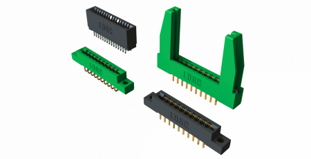
Card Edge Connectors for SSL Applications

Introduced to the market more than 50 years ago to connect the printed circuit boards of early computer systems together, card edge connectors have remained relevant and continue to be employed in a wide range of modern technology, including solid-state lighting. Originally used to facilitate connections between mother and daughter boards, card edge connectors also established expansion slot standards for PCI, PCI Express, and AGP cards and served as the basis for early consumer video game cartridges. Since then, card edge connectors have evolved to keep pace with the technological developments that have reshaped the electronics industry over the past half-century. Consisting of a single female connector that mates to exposed PCB contact pads processed into the edge of a mating printed circuit board (hence the name), card edge connectors continue to be modified to suit modern applications for three main reasons: simplicity, reliability, and cost effectiveness.

As the electronics industry evolved over the past few decades, card edge connectors were constantly challenged towards higher pin counts and higher signal speeds capable of supporting computer signal level advancements, which was a natural design progression. More recently, however, modern applications like solid-state lighting challenged card edge connectors to provide increased current and voltage levels capable of supporting industrial level performance, the complete opposite of the electrical specifications they were originally designed to provide, so that the rapidly expanding SSL industry could take advantage of the technology’s proven reliability while also making strides toward satisfying cost-competitive consumer product pricing demands. Due to the inherent simplicity of card edge connector designs, these specifications were primarily achieved by altering the contacts, which are the key to any reliable and robust connector system.


Figure 1. AVX 00-9159 Series single piece inverted through board card edge connectors mate perpendicular PCBs to a top-mounted main FR4 or metal core PCB from the bottom side, which is a common configuration in the LED bulb market. Available in two to six positions, they also offer added design functionality, such as color control or specific control lines.

Traditional card edge connectors were made with high spring force contact materials designed to accept multiple mating cycles and compensate for a larger tolerance range of mating PCB thicknesses. Newer card edge connectors designed for use in SSL applications have been developed using beryllium copper (BeCu) contact materials and are often stamped and formed to create the final contact geometry. BeCu has proven to be the best contact material on the market in stamped contacts, providing high spring force without yielding to the elevated temperatures, a large contact deflection range, substantial insertion force tolerance, and long-term reliability. One example of a BeCu card edge connector created specifically for SSL applications is AVX’s 9159 series vertical top and inverse mating connectors for perpendicular applications. Featuring a gold-to-gold active contact mating interface to maximize the mechanical and environmental performance of the connector system, 9159 series connectors provide a minimum of 10 mating cycles while supporting a UL rating of 2A per contact and 300V. Advantages that stamped and formed BeCu card edge connectors like these provide over conventional SMT card edge solutions include: multiple position offerings, up to twice the position density and current capacity, higher voltage ratings, compatibility with several PCB thicknesses, higher maximum operating temperatures, and improved electrical characteristics. Some newer card edge connectors for SSL applications, including the 9159 series, also offer optional versus integrated safety caps to achieve height reductions of up to 33 percent, which makes them much less likely to interfere with light output—a primary concern in SSL designs.


Figure 2. AVX 9159 Series card edge connectors feature gold plated BeCu spring contacts, which provide high spring force without yielding to the elevated temperatures, a large contact deflection range, substantial insertion force tolerance, and long-term reliability.

Other card edge connectors designed for use in SSL applications utilize phosphor bronze contact materials, which are slightly cheaper than BeCu contacts, but have a smaller deflection range. These contacts tend to use edge stamped contact technologies instead of traditional cantilever beam technologies and do not require any secondary forming. Much more rigid than cantilever beam contacts, phosphor bronze edge stamped contacts exhibit a high spring force with a lower spring deflection range, which requires tighter tolerance mating PCBs. Additionally, due to their high force, the number of mating cycles for edge stamped contacts is typically reduced to somewhere around five, or roughly half that of stamped and formed BeCu contacts. Phosphor bronze contacts and edge stamped technology are not new to the interconnect industry. Phosphor bronze is widely used in myriad applications, and edge stamped technology has long been used in FFC/FPC and other card edge configurations. Due to the high/rigid force that these contacts provide, tin plating is often used as a lower cost alternative to the gold plating used for BeCu contacts. The key parameter in any tin-to-tin contact interface is the amount of contact force required to both wipe the contact surface clean during the mating process and to maintain that force throughout the life of the product, which is roughly three to 10 times the force required of a gold interface. One example of card edge connectors that incorporate phosphor bronze contacts and edge stamped technology is AVX’s 70-9159 series coplanar contacts, which is extensively employed in end-to-end strip lighting applications. The UL current ratings for this series range from 2.5 to 3A per contact and 300V depending on the density and pin count of the chosen connector.


Figure 3. AVX 00-9159 open-ended card edge connectors provide higher pin count density and a smaller footprint than existing coplanar board-to-board card edge connectors, reliably connecting two PCBs in a cost effective, assembled solution and enhancing the flexibility with which engineers can mix and match power and signal lines.


Figure 4. AVX’s 00-9159 Series standard board-to-bard card edge connector provides a simple, reliable, and low cost solution for mating PCBs end-to-end in linear SSL strip lighting. The single, stamped contacts have dual contact beams to guarantee high force on standard 1.6mm PCBs and are available in two through five positions on 2mm pitch centers and provide a 3A continuous rating.


In sum, although card edge connectors are one of the more historic connector technologies, their proven simplicity, reliability, and cost effectiveness has encouraged engineers to continually create new card edge connector products designed to meet the performance standards for a variety of modern electronics. Now broadly employed in SSL applications to connect the power and ground signals of LED-to-LED or driver-to-LED boards, a host of proven, reliable, and robust low pin count card edge connectors from a variety of manufacturers are readily available on the market. Standard product sizes typically range from 2p to 6p, and expanded sizes up to 10p, which are ideal for linear lighting applications, are also available from several manufacturers. Further, card edge connectors suited for both metal core and FR4 PCBs, which are growing in SSL popularity due to the fact that newer LEDs consume less power and generate less heat for the same light output than they did even just a few years ago, and widely available as well.

Categories Blog

Extending Dim Range with Phase-Cut Dimmers

Users quickly notice shimmer and flicker in LED lighting. The strobing effect that is generated by misfiring phase-cut dimmers is unacceptable to end-users and dimmable bulbs that don’t work with a majority of local dimmers will not be successful.

Dimming range – the minimum (and maximum) output light that can be delivered by the lamp when connected to a dimmer – is also an important characteristic for LED light bulbs. At the bottom end of the dimming range an LED bulb will have either turned off, or reached minimum light output. Dimming range is usually expressed as a ratio of maximum to minimum light output. Driver manufacturers tend to look at the output current ratio as an approximation of dimming range.

The typical dimming range requirement for leading-edge TRIAC dimmers is a 10:1 current step; for trailing edge dimmers the figure is above 5:1. To understand what controls dimming range and why the accepted performance for leading-edge and trailing-edge dimmers is different, it is necessary to understand how minimum output current is achieved in a phase-cut dimmer.


Figure 1. The effect of TRIAC dimming angle on LED driver output current

Trailing-edge dimmers use internal logic circuitry to control the dimming angle which requires power. This power is delivered to the driver when the TRIAC is turned-off (not delivering power to the lamp). To ensure this happens, trailing-edge dimmers tend to have higher dimming angle than equivalent leading-edge types.

Typically this was not a problem with incandescent bulbs because their light output changes exponentially with power at low brightness levels (the bulb gives very little light output at low conduction angles) which means low brightness occurs significantly above the limit the power storage requirement imposes.


Figure 2. Maximum and minimum dimming angles for highline dimmers (Source: Power Integrations) – The range of maximum and minimum dimming angles makes wide dimming range challenging

Controlling factors for dimming range
The red trace in figure one shows an LED driver output current that is directly proportional to the conduction angle. The LED load takes a high load current even at relatively low conduction angles, but does not reduce current sufficiently by the time the minimum conduction range for TRIAC dimmer is reached. The high load current delivered using this approach means that TRIACs will see high holding currents, reducing the likelihood of shimmer or flicker.

The designer can elect to increase the dimming-slope of the LED driver to arrive at a lower output current at a higher dimming angle (blue trace in figure 1). This allows the bulb to dim to a lower brightness but risks causing shimmering and/or flickering as the load current drops. In a practical design this means that a significant amount of extra power must be drawn by a bleed circuit to keep the TRIAC from misfiring (this region is shown in red area in figure 1). This reduces driver efficiency making the need for heat sinking or potting materials more likely in the final design.

An alternative approach is to employ an adaptive bleeder circuit such as shown in the driver in figure 3. The bleeder circuit draws more current in deep dimming to compensate for the reduced output current but preventing excess heating at full brightness


Figure 3. Dimmable bulb driver with smart (lossless) bleeder function. The driver also shuts off at very low output current (deep dimming) to reduce the risk of TRIAC dimmer misfiring and causing shimmer (http://led-driver.power.com/sites/default/files/PDFFiles/der409.pdf

Dimming range, like so many of the design considerations for a TRIAC dimmable LED driver, cannot be considered in isolation. A design requirement that pushes for excellent dimmer compatibility and extended dimming range will (with presently available driver circuitry) lead to increased solution cost.

Categories Blog

Great Achievements Inspire Greater Expectations

Not since the Chicago World’s Fair in 1893 when President Grover Cleveland pushed a button to light 100,000 incandescent lamps to create the “City of Light” has the lighting industry experienced the global attention that it has today.  We have recently witnessed a Nobel Peace prize in Physics for LED lighting in recognition that LED lamps hold great promise for increasing the quality of life for over 1.5 billion people around the world who lack access to electricity grids.  In addition, the United Nations has declared 2015 to be the International Year of Light to raise awareness of how light and optical technologies promote sustainable development and provide solutions to worldwide challenges in energy, education, agriculture, communications and health.  These are momentous occasions, and they occur at a time when consumer awareness of LEDs has never been higher.  However, as LEDs continue to become more mainstream and our industry garners more attention and recognition, this is leading to even higher expectations from us and the future of the lighting.

Though light bulbs and switches have historically represented the way most people think about lighting – a basic, mechanical tool that we use for illumination – the UN realized that lighting has become so much more. Driven by solid state lighting technology, lighting is on the cusp of playing an entirely new role in our lives.  Though our industry’s relentless pursuit of energy efficiency has been quite successful, sustainability has become commoditized, and we’re already starting to feel the reality of diminishing returns. The rise of tunable color technology is an example of the added value we’re already seeing from SSL, but it is only a matter of time before it becomes a commodity as well.

The light quality and price of LED lamps have reached a point where these products have become a real alternative for consumers, who have never been more educated about the lighting choices available to them. As we continue to introduce a broader portfolio of LED products and innovative technology to the consumer market, adoption of these products will accelerate much faster as we approach the tipping point to SSL, creating exciting growth opportunities for LEDs in the consumer and commercial markets.

Above all, one thing is clear: the future of lighting is a bright one and we are certainly heading in the right direction. As we look ahead to 2015, we should not only be proud of our ability to adapt within our industry, we should ensure we’re thinking bigger than tunable light and energy efficiency. Light is getting smarter, and we need to start envisioning the opportunities that smarter lighting can offer as we mold it into our world and our lives. Today’s SSL innovations are already changing the way we work, shop, eat and live – tomorrow’s challenge will be to push the boundaries of our industry’s imagination in a way that is worthy of the UN’s global celebration of light and light-based technologies.