The installed base of domestic dimmers supports the almost ideal resistance exhibited by the impedance of an incandescent bulb. These devices are increasingly called upon to support LED replacement lamps, which offer challenges unanticipated by the designers of the dimmer systems, such as low current draw and very fast luminous response to minor power fluctuations. This blog highlights how dimmer type determines both the selection of damper and bleeder circuits in LED drivers, and the switching topology needed to optimize operation.
Phase-cut dimmers, either leading-edge or trailing-edge, make up the bulk of the dimmer market. After the input voltage rises following the zero crossing, leading edge dimmers inhibit for a period of time, controlling energy transferred to the lamp load and hence output brightness. Trailing-edge dimmers also regulate output by inhibiting for a period of time, however this is referenced to the negative going edge of the half-cycle.
Leading-edge dimmers are typically lower cost and so are more widely used whereas trailing–edge dimmers exhibit lower EMI and are preferred in some markets (notably Europe) and noise sensitive environments. That-being-said, it is unlikely that the average consumer will know whether their fixture is controlled by a leading-edge or a trailing-edge dimmer, and so it is important that LED replacement bulbs work with both types.
Figure 1. Simplified schematic of a leading-edge phase-cut dimmer (Including transient and surge suppression elements LS and CS)
Figure 2. Simplified schematic of a trailing-edge, phase-cut dimmer
Why shimmering and flickering occurs in leading-edge dimmers and why leading-edge and trailing-edge dimmers respond differently
In leading-edge phase-cut dimmers, the switching element is typically a TRIAC. Unlike BJTs or MOSFETs the TRIAC will latch-on once it is energized (after forward current exceeds latching current). It will continue to conduct until the forward current drops below a threshold (holding current). The TRIAC is protected against input voltage surges by a bypass capacitor CS and from high transient currents at switch-on by a series inductance (LS). The installed base of TRIAC dimmers in use today are designed to work with an almost ideal resistance (an incandescent bulb). The bulb presents a very-low impedance during turn-on, latching the TRIAC (IF>>IL) and once in conduction allows current to flow to zero crossing which holds the TRIAC in conduction (IF > IH) for almost the whole AC half-cycle. With no capacitive or inductive elements, the incandescent bulb does oscillate when presented with the voltage step of a dimmed AC sine wave. Because the TRIAC-dimmer/incandescent-bulb interface is not sensitive to the LS and CS values, the values of these components are not constrained and vary significantly between different leading-edge dimmer designs.
At turn-on, an LED load presents relatively high impedance, so input current may not be sufficient to latch the TRIAC dimmer. In order to insure that IL is achieved, a bleeder circuit is typically added to the LED driver input stage. In the simplest form, the bleeder is a simple RC combination that insures a pulse of current when the input voltage is applied.
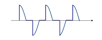
An LED lamp load does not exhibit incandescent-like pure resistance, and so, when presented with a step voltage the EMI filter and the bulk capacitance of the switching stage will cause an oscillation in the input current (IF) (see figure 3). The amplitude of the load ring is modulated by the surge protection capacitor CS, making the amplitude of the oscillation dependent on dimmer type.
Figure 3. Typical input current waveform for a power-factor-corrected dimmable bulb showing the oscillation caused by input current dropping below IH
To reduce the ring, a damper circuit is added – in its simplest form a series resistance to reduce the amplitude of oscillation at the expense of reduced efficiency (and therefore more heat for the LED bulb enclosure to manage). The LED Bulb designer must add the smallest amount of damping impedance at the input stage of the LED that will allow the LED bulb to remain above the minimum holding current. Different leading-edge dimmers have different values for CS and LS which act to modify the current ring on the TRIAC. The TRIAC in each dimmer type will see more ringing than would be seen at the bulb due to LS. The designer must allow sufficient margin (give up efficiency) in the damper circuit to work with as many dimmers as practicable.
To further enhance damping, a bleeder is needed to compensate for, or mask the ringing below, the holding current. A simple RC bleeder is used across the input line or after the bridge rectifier. The bleeder is optimized with respect to the power rating of the LED driver. For lower power LED lamps higher bleed is required.
Trailing-edge dimmers present a different set of problems
The input voltage waveform from a trailing-edge dimmer is sinusoidal at the start of each half-line cycle. The MOSFET switch is driven by a controller which continually energizes the gate, making the dimmer less susceptible to current ringing.
However, the power supply in the LED will present a high impedance to the dimmer when the MOSFET switch is opened to cut power delivery. Trailing-edge dimmers require the input voltage of the LED driver to fall to zero each half-cycle to enable the dimmer controller to energize its own supply rails. This ensures that the zero-crossing detector will turn on the switch at the beginning of the next voltage half-line cycle. If there is insufficient impedance to bleed down the dimmers output voltage before the next AC cycle begins, then the dimmer may misfire causing shimmer and flicker.
Figure 4. For a trailing-edge dimmer if insufficient current is drawn to force a zero-crossing before the next half-line cycle, the dimmer may misfire, causing shimmer or flicker
Buck converters in particular have challenges when supporting trailing-edge dimmers. Buck converters are very popular for LED lamp drivers due to their high efficiency and low component count. For a buck topology, when the input voltage falls below the output voltage, the switching circuit cannot draw any power from the AC rail (and is therefore unable to bleed down the switch voltage). In contrast, buck-boost, tapped-buck and flyback converters can draw current for the entire switching cycle. For this reason, buck-boost converters and tapped-buck drivers with ICs, which switch through the whole line cycle as the LYTSwitch-4 from Power Integrations, can pull down the dimmer voltage after it turns off and are therefore better able to support trailing-edge dimmers.
Figure 5a. Buck Converter – Excellent with Leading-edge dimmers. MOSFET D-S is reverse biased when the input voltage drops below ~48 V. The passive bleeder (C8/R6) is required to provide the low impedance path between line-neutral to force zero crossing of the input voltage to work with trailing-edge dimmers.
Figure 5b. A Buck-boost converter continues switching (provides a low impedance) to the input when the input voltage has fallen below output voltage, making this topology more suitable for trailing-edge dimmers
Conclusion
Bleeder and damper circuits can be tuned to accommodate almost all leading-edge phase-cut dimmers. The designer trades off efficiency in order to achieve best possible dimmer compatibility but is not able to guarantee performance due to the variability of dimmer component values. Practical designs usually accommodate trailing-edge dimmers. In order to work with trailing-edge dimmers, further compromise on efficiency (large bleed current) or even a change in topology may be required in order to achieve acceptable dimmer compatibility in a given bulb design.