Categories Blog

Understanding Consumers and Their Sockets

 The lighting industry has never been more alive.  The business is evolving faster with new opportunities and technologies every day and in my new role as the global CEO of the lamps business at OSRAM, I have the privilege of leading our journey into this exciting future.  The sweeping, dynamic innovation of the lighting industry is challenging how we do business from product development to consumer and customer engagement. That is why it has never been more important to understand what consumers know – and don’t know – about LED lighting technology.

Recently, we released the results of this year’s edition of the OSRAM SYLVANIA Socket Survey, a report that examines consumer awareness, adoption and understanding of lighting technology. Now in its seventh year, the survey has evolved from initially helping us understand how aware and prepared consumers were for the phase out of incandescent bulbs to current research more heavily focused on LED lighting and smart, connected lighting technology.

I am pleased to report that consumer adoption of LEDs is on the rise as 65 percent of Americans surveyed have purchased LEDs for use in their homes and the majority (64 percent) of those who did, purchased LED bulbs for use in sockets. Of the respondents who were identified as LED bulb users, the most valued benefits of making the switch were reduced energy consumption (96%), longer bulb lifespan (93%) and cost savings (93%).  As the price of LED lighting continues to come down, what was perhaps a prohibitive barrier is beginning to be perceived as a value, with 86 percent of Americans who have purchased LEDs believing the initial cost was worth it.  Consumers like what they’re seeing, which underscores how important it is for us to continue delivering quality LED products to the market.


From FitBit to Nest, the Internet of Things continues to take the world by storm, and the lighting industry is no different. Smart lighting is the next big frontier and awareness of this technology is high at 62 percent of those surveyed.  However, we’re still very early in the adoption cycle, with only one in 10 reporting they have purchased smart lighting products. Fortunately, consumers who are interested in the smart, connected home understand the role and value that lighting can provide, as 83 percent of those surveyed believe that smart lighting is a good introduction to home automation technologies.

There are certainly areas of opportunity for improvement, and consumer education is always a priority. Though we’ve seen great progress with virtually all survey participants (99%) aware of LED lighting versus only 69 percent in 2012, consumers’ top sources of information about lighting products continue to be in-store displays, retail employees and product packaging. Our industry’s evolution certainly isn’t slowing down, which makes educating consumers all the more important to continue today.  By partnering closely with the retail industry, we can work to ensure that purchasing decisions around lighting are as informed as possible.

The future will continue to bring new and exciting innovation, not only in technology but also in our understanding of how lighting impacts our productivity, health and well-being. Today, consumers recognize poor lighting when they see it, but they can’t necessarily articulate what makes for ‘good’ or ‘appropriate’ illumination. Imagine a world where we won’t need to think about our lighting at all because it will adapt to our behavior, the task at hand, the time of day and the setting. As we continue to inject software-fueled intelligence into our lighting systems, it’s clear that future has arrived.

Halfway into what the United Nations has named the International Year of Light, the Socket Survey shows that we’re making positive progress and guides us to where work still needs to be done.   Looking ahead, I can’t help but feel confident about where we are and where we are going.

Categories Blog

Seeing is Believing


Congregations are realizing they have a responsibility to set an example and be stewards of the earth. While environmental stewardship may be implemented in a variety of programs such as purchasing eco-friendly cleaning supplies, planting an organic flower and vegetable garden on the grounds, and recycling, the opportunity with the largest potential impact on the bottom line is energy conservation.

There are approximately 350,000 houses of worship in the United States. Energy use represents the greatest negative environmental impact of the average house of worship.[1] Greenfaith, an interfaith coalition for the environment, believes it’s time for communities of faith to become leaders in the fight against climate change through energy conservation – saving valuable funds to invest in religious activity and outreach.

According to the US Environmental Protection Agency, congregations collectively spend close to $2 billion on energy annually and energy costs are the second highest fixed cost after personnel. But energy use, specifically lighting, is a way to reduce costs. Tremendous advances in technology and engineering make it possible to achieve a significant reduction in energy use and expenditures. Most congregations can cut utility costs by up to 30 percent through strategic investment in energy efficiency.[2]

If America’s houses of worship reduced their energy usage by just 10 percent:

  • Nearly $200 million could be saved
  • More than 5.4 billion in kWh would be available without additional cost or pollution
  • More than 2 million tons of greenhouse gas emissions would be prevented [3]

Religious Organizations Take the Lead
Numerous religious organizations are in the forefront of energy conservation. For example, Interfaith Power and Light (IPL), is an organization that began in California in 1998 whose mission is “to help churches become good stewards of the earth.” To become a member, churches must sign a covenant and pledge to “green” their congregations through various means. Churches who sign IPL’s covenant gain access to resources like a professional energy audit, and support to make changes that can add up to lower bills, less energy waste and a more informed congregation.

The Sustainable Sanctuary Coalition “assists faith groups to preach, teach, model and advocate for sustainable living and ecological justice for all creation. The group works to extend a helping hand to congregations of all denominations that are interested in going green but don’t know where to start.”

Another example is Philadelphia’s Interfaith Coalition on Energy, comprised of the city’s Archdiocese, Board of Rabbis and the Metropolitan Christian Council. The organization’s mission is to inspire congregations to reduce the costs of operating their facilities by guiding them to use measurably less energy and to purchase energy at lower cost.

In a 2008 survey by the National Association of Temple Administrators, nearly 95 percent of Reform (Judaism) congregations in North America have investigated or initiated some form of greening their facilities; and of those that have engaged in major construction recently, 64 percent attempted to use sustainable materials.

The General Convention of the Episcopal Church passed a resolution in 1997 calling on members to practice energy efficiency in response to climate change concerns. Leaders in the Church established Episcopal Power and Light to combine the purchasing power of churches and their congregations to buy green power. The aim was to unite communities, empower congregations, and build bridges among different religions with the goal of reducing the threat of climate change. The US National Council of Churches, with about 340,000 congregations, and the World Council of Churches are developing similar programs.

These are just a few of the many faith-based organizations leading the drive to reduce congregations’ energy consumption and expenses.

The Calling
Demand for sustainable houses of worship is being driven on multiple fronts. The need for healthier environments, the role that religious institutions should play to lead this charge, and the ever increasing energy prices, coupled with a challenging economy, has grabbed the attention of congregations’ clergy and lay leaders. But certainly not all 350,000 congregations are looking to build new, sustainable facilities; many are in need of smaller-scale ways to reduce energy costs.

Typically, lighting can account for a large portion of a congregation’s electricity cost. This means that significant cost savings can be achieved with energy-efficient improvements, and due to continually improving technology, lighting usually provides the highest return-on-investment of major upgrades.[4]

Parking Lot Illumination
One key to making day-to-day operations more energy efficient and more sustainable is through the installation of exterior LED luminaires. Most congregations have parking lots that require illumination and use traditional parking lot lights that consume a staggering 22.2 billion kilowatt-hours per year.[5] Parking lot energy needs could be reduced by more than 40 percent, and maintenance costs could potentially be cut by more than 80 percent with the installation of LED lighting, according to the US Department of Energy.

[1] www.greenfaith.org “Energy Conservation.”
[2] National Council of Churches’ “Bottom Line Ministries that Matter.”
[3] “Congregations: An Overview of Energy Use and Energy Efficiency Opportunities,” Environmental Protection Agency, NationalServiceCenter for Environmental Publications.
[4] Energy Star®: “Putting Energy ito Stewardship, Congregation Guide.” December 2007
[5] Facilities Engineering Journal, March/April 2009 issue, page 34, “Parking Lot Lighting System Saves Energy.”

Categories Blog

SSL-Specific Connectors, Why are they Different?

As lighting designers, you’ve probably faced the inevitable decision of what connectors to use in your latest fixture design. You go to a website or open up a catalog and you’re faced with a broad and sometimes dizzying array of connectors to choose from.  If you’re early enough in the design process, there’s typically a pretty broad range of connectors that you can consider for your application. On the other hand, if you’re a designer that waits to the end to select connectors, your options can be pretty limited due to board layout constraints and configuration of components.

A number of the connectors you’ll come across in a general search were, in all probability, developed for some other application in a completely different industry. Could you get them to work in your application? Yes, maybe. Would they be an ideal fit? Well, therein lies the potential problem.

Let’s say you need a wire to board connector with a header that sits on the edge of the PCB along with a mating direction parallel with the board. You pull up the TE website and after using our product selector to isolate desired performance characteristics, you find our TE Micro MATE-N-LOK. It is a small, compact 3 mm centerline product that’s been on the market for years. At first glance, it has the voltage and current capability you need and it looks like it would fit your application from a foot-print standpoint. You pull up the customer drawing on the first part number listed and notice two things: 1) The housing is black and, 2) the latch on the top of the connector is 8.7 mm above the board.  You quickly conclude this connector is less than ideal since the height will probably mask light coming off your PCB mounted LEDs and secondly, the black housing won’t reflect the light further adding to the light blocking. All is not lost. Interestingly, if you scroll down the screen a little further, you’ll come across a variant that was designed specifically for SSL applications. It features a side latch design that lowers the profile to 5.26 mm and is molded of a white polymer to enhance reflectivity.  I’m sure you’ll agree the latter is a much better fit for your SSL design.

This is just one example of SSL specific connectors that enhance usability, performance, and assembly. Another example can be found in TE Connectivity’s standard and mini hermaphroditic connectors that were designed from the start for SSL applications. Targeted towards LED strip lighting, their unique multi-axis mating design allows a user to remove a single segment out of a series of LED strips without disconnecting and unfastening the entire series.  Because it is designed to mate to itself, a single part number can therefore be used on both ends of an LED strip. Try that with a pin and socket connector originally designed for a personal computer application!

So to close this blog, if you’re working on an SSL design, why not look at SSL-specific connectors first and early in the design process? If you don’t see something that exactly fits your needs, don’t hesitate to ask.  If you see something that almost fits your needs, ask about it as well since we at TE Connectivity aim to provide an extraordinary customer experience and are quite open to discussing variations of existing products to meet your specific requirements.  If you’d like to learn more about SSL lighting connectivity solutions or discuss Intelligent Buildings, please contact me at plieffrig@te.com.

Categories Blog

Enabling SSL Adoption Through Intuitive Interconnect – Part II

Last month we discussed interconnect of the Chip on Board LED device within a luminaire utilizing a TE Connectivity (TE) scalable or Zhaga compliant socket.  This month we’ll move another layer away from the light source and look at the various device-level interconnects commonly used in lighting applications. Lighting interconnects span a broad range of options from board-to-board, wire-to-board, surface mounted and inverted through board technologies.  The multitude of interconnect options for the fixture designer can be confusing, so let’s spend the time speaking about the attributes and merits of common interconnect classifications used in lighting systems.

Board-to-board applications: This connector technology allows the direct connection of two printed circuit boards. In lighting applications, this is usually in an end-to-end fashion. While a number of board to board options exist, a specific example shown is TE’s Hermaphroditic connector. This connector allows for end to end mating of board assemblies and also allows for horizontal and vertical axis mating enabling 90° and 180° articulation.  Linear, multi-segment, solid state lighting (SSL) board assemblies commonly used in cove lighting or linear lighting fixtures are ideal applications for this type of interconnect.

Wire-to-board applications: This category of interconnection can be further segmented into sub categories; two-piece separable, one-piece removable and one piece permanent. All accomplish the same fundamental task of bringing a wire to a printed circuit board in a simple, solderless approach. An example of a separable wire to board connector can be seen in TE’s low profile, micro MATE-N-LOK connector shown in the image at the right. A one piece removable solution is best illustrated by TE Connectivity’s innovative line of poke-in connectors that includes the micro poke-in wire SSL connector. Lastly, a one piece permanent connection between a wire and board can be accomplished with an insulation displacement connector such as TE’s SMT IDC connector. Termination with an IDC connector is as simple as inserting the un-stripped wire and pressing the stuffer cap down. The common thread shared by all these wire to board connectors is they are all low-profile wire to printed circuit board connectors designed specifically  for LED lighting systems whether they be channel lettering lighting strips, general illumination LED fixtures, architectural cove and valence lighting,  or LED modules for other applications.

There is another unique wire to board product that is worth noting here as well. The inverted through-board style of connector products provide an unobtrusive interconnect to printed circuit boards. By rotating the mating axis to mate from the underside of a PCB, connector exposure and wire routing issues on the LED side of the board are minimized.  The result is a clean, minimally obstructed light emitting surface ideal for use with LED array implementations in downlight, spotlight and even street-lighting applications.

To close, the interconnection is often one of the last items to be considered in a lighting design. The wrong selection can have long term ramifications in manufacturing, reliability and field repair. With a little forethought and understanding of interconnect options, design, assembly and repair can be optimized in lighting systems. Consider the following during your design efforts:

  • Is this a board to board application? If so, can this be accomplished with a direct board to board mating connector system or is a header/wire jumper assembly required by the application?
  • For wire to board applications is a separable wire to board interconnect required or can the wire be terminated with a one piece semi-permanent or permanent connector?
  • How many circuits need to be accommodated by the connector?
  • What is the end fixture application and what are the governing agency standards required by the fixture?
  • What is the voltage and current rating required?
  • What are the particular environmental constraints required (temperature, humidity, shock/vibration, ingress protection, etc.)?
  • Does your application require positive latching or is a friction latch acceptable?
Categories Blog

Which Driver Topology to Choose

Designing optimum LED drivers for Industrial, commercial and consumer applications requires a clear understanding of the application requirements. To achieve power factor correction, low total-harmonic-distortion (THD) and good output current control while meeting increasing cost and efficiency targets, only the most appropriate switching topology will suffice. Since there is no standardization in LED load voltage requirements, no single “best topology “exists. 

The aim of this month’s article is to explore off-line conversion and examine the factors that determine where buck, buck-boost, tapped-buck and flyback topologies are most effective.

Highest efficiency and lowest cost, input voltage range, output voltage range, THD, PF, regulatory requirements and the cost of isolated versus non-isolated topologies are all factors that need to be considered in selecting the appropriate driver.

Available Topologies
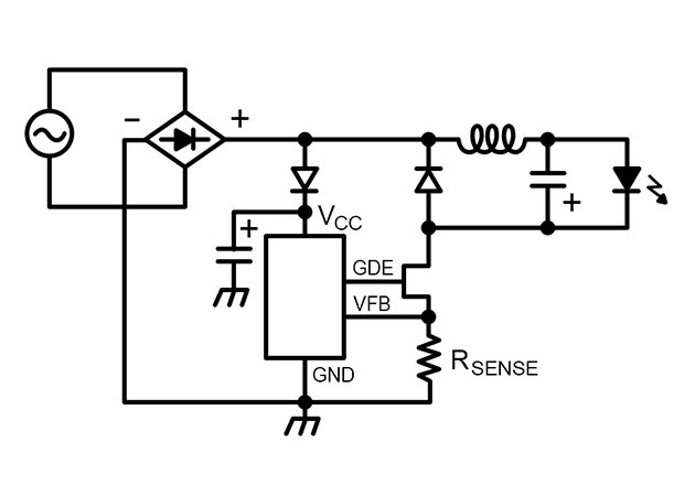
The simplest switching conversion approach is to use a buck converter – it has the lowest component count, a very simple (low cost) magnetic component (an inductor) and the highest efficiency.  The use of single stage combined PFC and CC controllers means that for PFC and low ATHD, buck converters are an attractive choice for non-isolated designs.


Figure 1. High-Side Buck Circuit using a Combined PFC and CC Output Integrated Control + Switching IC (Note that a high value aluminum electrolytic bulk capacitor is not required) [3]

Buck converters cannot provide functional isolation and requires the input voltage to be higher than the output voltage to work. The latter issue is important when considering THD. It can be shown that in order to meet EN61000-3-2 C/D standards for THD, the output voltage from a low-line input buck converter must be less than approximately 35 VDC. This limit is needed to keep the conduction angle (the proportion of the switching cycle over which the switching circuit is able to conduct and therefore influence input current wave-shape) high enough to effectively shape the input current to meet THD limits. For high-line applications, the maximum output voltage is approximately 70 to 75 V. In addition, Buck converters are not good at controlling voltage step-down if the ratio of input to output voltage is greater than approximately 8:1 due to duty cycle limitations in the controller.

Buck-Boost Converter
Buck-boost conversion is the next alternative – component count is similar to buck designs and efficiency is also very high. Buck-boost converters operate across a wider portion of the available conduction angle and so can provide good THD for higher output voltage designs. They have a similar problem with isolation and duty cycle limited input/output voltage ratio as buck converters.


Figure 2. Non-Isolated Buck-Boost Converter Employing Combined PFC and CC Single Stage Converter IC


Tapped-Buck Converters
The next category to consider as a possible solution is tapped-buck converters. The more complex winding structure of the magnetic element introduces a cost and efficiency penalty. However the transformer/inductor nature of the winding structure allows a turns-ratio type adjustment of output voltage and current, making tapped buck converters good for standard designs where the input to output ratio precludes the use of a buck or buck-boost topology. It is appropriate to consider the tapped buck converter as analogous to a non-isolated flyback converter


Figure 3. A low Power Tapped-Buck Converter (With no PFC stage)
Note the Wide-Input Voltage Range


Flyback Converters
The final category of LED driver we will consider is the flyback converter. The converter can be implemented as either isolated or non-isolated and the turns-ratio capability of the transformer allows for pretty much any ratio of input to output voltage. Due to imperfect coupling between primary and secondary windings, as well as primary parasitic capacitance, the more complex winding arrangement leads to increased cost and power losses. Flyback converters are overwhelmingly used for isolated LED bulb designs and use either a passive-valley fill PFC circuit (Valley fill is acceptable for 0.7 PF applications but induce 8 to 10 percent efficiency penalty in reaching the 0.9 PF required for commercial applications), or higher-efficiency combined CC and PFC converters that are available today.


Figure 4. High Efficiency Combined PFC and CC Converter in an Isolated Flyback Topology


Choosing the Right Topology
A summary of the decision process to select between different topologies is shown below. The selection strategy assumes the following order for designs: Buck →Buck Boost →Tapped Buck → Flyback. The order is weighted; highest efficiency and lowest cost being the most desirable requirements.


Figure 5. Topology Selection Flow Chart

Only if the best topology for each design is selected, can performance be guaranteed and the best design delivered. Every design will be different but all can follow the methodology described in this paper for deriving the most ideal solution for each application type.

Categories Blog

Better than L70 for Interior Spaces?

Those of us who have been pushing solid state lighting for the past six-plus years are used to preaching about its benefits of high efficiency, fine optical control and expected lifetimes greater than anything else available.  Why?  Because from A-lamps to area lights, we need to communicate an intrinsic benefit to asking for the 2X-20X premium over the incumbent technology.  Outdoor lighting specifications, which have been predominantly based on HID sources, are quite rapidly changing to solid state lighting because a solid ROI can be communicated on those three aspects. It’s a tougher case for solid state lighting in conditioned interior applications where the efficient (and inexpensive) linear fluorescent is currently king. Solid state lighting manufacturers rely on the newly-attainable efficiency gains over fluorescent luminaires as the primary value proposition.  However, a rumbling of lumen maintenance claims as high as L90 are beginning to emanate from lighting manufacturers in an effort to add value to interior solid state lighting.  Is this all smoke and mirrors, or is there legitimate value for a L90 lifetime specification?

LED lifetime for general lighting applications is traditionally defined as the L70 lumen maintenance point, at which time the light output has depreciated 30 percent from its original value.  The industry settled upon this point for defining lifetime because it represented the threshold of the human eye for detecting reductions in light output.  Was this a little overzealous?  Probably, but we needed something.  At least with L70, there would be a perception of depreciation, although over the five-plus years of operation, it would be quite difficult to detect.  Should L90 ever be adopted, we’re essentially declaring end-of-life before the eye can ever see a difference!  Pretty ironic indeed.

Admittedly, this is not new.  L90 is clearly in response to the newer 800 series T8 lamps that are claiming L90+ lumen maintenance over 40,000 hour-plus periods.  Should this be the benchmark?  Let’s keep in mind that these values are really only possible on a bench top.  A T8 lamp produces its peak lumens at a 25°C ambient and a T5HO at 35°C.  The problem is, the luminaire enclosure, surrounding optics and environmental ambient rarely, if ever, keeps the lamp even close to these temperatures!  A brand-new linear fluorescent troffer or suspended direct-indirect could, in-fact, begin its life well below L90, but this fact can be hidden in relative photometry.  Did we care (or even notice) then?

The temperature dependency of LED sources is why absolute photometry is specified by IESNA LM-79.  It certainly provides for more accurate light output from the luminaire, but it is not without its own demons that will be problematic for a legitimate L90 specification—that necessary evil known as binning.  Despite the diligent efforts of LED manufacturers to control their processes from die fabrication to packaging, all LEDs have some variation in terms of chromaticity and flux that must be tested and quantitatively grouped, or binned, into a predetermined range of values.  This range of values is usually a 10 to14 percent variation on flux.  The luminaire manufacturer then procures the LEDs to that binning specification, which will contain discrete LEDs of all values in-between.  On top of that, every LED manufacturer claims a measurement tolerance of 5 to 7.5 percent on their flux measurement.  All of this potential variation together means it’s very possible that a brand new LED luminaire will leave the factory well below L90!

Whether or not the products ship out of the factory at full output or below L90, there is a high probability that it will not be caught and relamped.  Why?  Because the only approved method for assessing LED luminous flux will be to test each product in an integrating sphere by a laboratory certified to conduct LM-79 testing.  To that extent, products will likely not even undergo a re-lamping at L70 since it’s still not to a point where users will find the lighting uncomfortable, let alone any clear indication that end-of-life has been reached.  Lumen maintenance is not a definite point in time that can be marked with a calendar—it’s a function heavily dependent on tens, if not hundreds, of variables not accounted for in any end-of-life projection.

L90 sounds really appealing on paper, whether it’s LED or fluorescent, especially within the game that is specification lighting.  When initial output and end-of-life lie so closely together and warranties are established around those qualities, that manufacturer is accepting a very high degree of risk in order to capture a bit of attention.  We can’t fault them for that, but let’s have a realistic expectation of what the technology is capable of providing and make sure there is actual value provided that offsets the risk. This isn’t uncharted territory.

Categories Blog

Leading-Edge vs. Trailing-Edge Dimmers

The installed base of domestic dimmers supports the almost ideal resistance exhibited by the impedance of an incandescent bulb. These devices are increasingly called upon to support LED replacement lamps, which offer challenges unanticipated by the designers of the dimmer systems, such as low current draw and very fast luminous response to minor power fluctuations. This blog highlights how dimmer type determines both the selection of damper and bleeder circuits in LED drivers, and the switching topology needed to optimize operation.

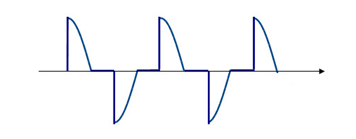
Phase-cut dimmers, either leading-edge or trailing-edge, make up the bulk of the dimmer market. After the input voltage rises following the zero crossing, leading edge dimmers inhibit for a period of time, controlling energy transferred to the lamp load and hence output brightness. Trailing-edge dimmers also regulate output by inhibiting for a period of time, however this is referenced to the negative going edge of the half-cycle.

Leading-edge dimmers are typically lower cost and so are more widely used whereas trailing–edge dimmers exhibit lower EMI and are preferred in some markets (notably Europe) and noise sensitive environments. That-being-said, it is unlikely that the average consumer will know whether their fixture is controlled by a leading-edge or a trailing-edge dimmer, and so it is important that LED replacement bulbs work with both types.


Figure 1. Simplified schematic of a leading-edge phase-cut dimmer (Including transient and surge suppression elements LS and CS)


Figure 2. Simplified schematic of a trailing-edge, phase-cut dimmer


Why shimmering and flickering occurs in leading-edge dimmers and why leading-edge and trailing-edge dimmers respond differently
In leading-edge phase-cut dimmers, the switching element is typically a TRIAC. Unlike BJTs or MOSFETs the TRIAC will latch-on once it is energized (after forward current exceeds latching current). It will continue to conduct until the forward current drops below a threshold (holding current). The TRIAC is protected against input voltage surges by a bypass capacitor CS and from high transient currents at switch-on by a series inductance (LS). The installed base of TRIAC dimmers in use today are designed to work with an almost ideal resistance (an incandescent bulb). The bulb presents a very-low impedance during turn-on, latching the TRIAC (IF>>IL) and once in conduction allows current to flow to zero crossing which holds the TRIAC in conduction (IF > IH) for almost the whole AC half-cycle. With no capacitive or inductive elements, the incandescent bulb does oscillate when presented with the voltage step of a dimmed AC sine wave. Because the TRIAC-dimmer/incandescent-bulb interface is not sensitive to the LS and CS values, the values of these components are not constrained and vary significantly between different leading-edge dimmer designs.

At turn-on, an LED load presents relatively high impedance, so input current may not be sufficient to latch the TRIAC dimmer. In order to insure that IL is achieved, a bleeder circuit is typically added to the LED driver input stage. In the simplest form, the bleeder is a simple RC combination that insures a pulse of current when the input voltage is applied.

An LED lamp load does not exhibit incandescent-like pure resistance, and so, when presented with a step voltage the EMI filter and the bulk capacitance of the switching stage will cause an oscillation in the input current (IF) (see figure 3). The amplitude of the load ring is modulated by the surge protection capacitor CS, making the amplitude of the oscillation dependent on dimmer type.


Figure 3. Typical input current waveform for a power-factor-corrected dimmable bulb showing the oscillation caused by input current dropping below IH

To reduce the ring, a damper circuit is added – in its simplest form a series resistance to reduce the amplitude of oscillation at the expense of reduced efficiency (and therefore more heat for the LED bulb enclosure to manage).  The LED Bulb designer must add the smallest amount of damping impedance at the input stage of the LED that will allow the LED bulb to remain above the minimum holding current. Different leading-edge dimmers have different values for CS and LS which act to modify the current ring on the TRIAC. The TRIAC in each dimmer type will see more ringing than would be seen at the bulb due to LS. The designer must allow sufficient margin (give up efficiency) in the damper circuit to work with as many dimmers as practicable.

To further enhance damping, a bleeder is needed to compensate for, or mask the ringing below, the holding current. A simple RC bleeder is used across the input line or after the bridge rectifier. The bleeder is optimized with respect to the power rating of the LED driver. For lower power LED lamps higher bleed is required.

Trailing-edge dimmers present a different set of problems
The input voltage waveform from a trailing-edge dimmer is sinusoidal at the start of each half-line cycle. The MOSFET switch is driven by a controller which continually energizes the gate, making the dimmer less susceptible to current ringing.

However, the power supply in the LED will present a high impedance to the dimmer when the MOSFET switch is opened to cut power delivery. Trailing-edge dimmers require the input voltage of the LED driver to fall to zero each half-cycle to enable the dimmer controller to energize its own supply rails. This ensures that the zero-crossing detector will turn on the switch at the beginning of the next voltage half-line cycle. If there is insufficient impedance to bleed down the dimmers output voltage before the next AC cycle begins, then the dimmer may misfire causing shimmer and flicker.


Figure 4. For a trailing-edge dimmer if insufficient current is drawn to force a zero-crossing before the next half-line cycle, the dimmer may misfire, causing shimmer or flicker

Buck converters in particular have challenges when supporting trailing-edge dimmers. Buck converters are very popular for LED lamp drivers due to their high efficiency and low component count. For a buck topology, when the input voltage falls below the output voltage, the switching circuit cannot draw any power from the AC rail (and is therefore unable to bleed down the switch voltage). In contrast, buck-boost, tapped-buck and flyback converters can draw current for the entire switching cycle. For this reason, buck-boost converters and tapped-buck drivers with ICs, which switch through the whole line cycle as the LYTSwitch-4 from Power Integrations, can pull down the dimmer voltage after it turns off and are therefore better able to support trailing-edge dimmers.


Figure 5a. Buck Converter – Excellent with Leading-edge dimmers. MOSFET D-S is reverse biased when the input voltage drops below ~48 V. The passive bleeder (C8/R6) is required to provide the low impedance path between line-neutral to force zero crossing of the input voltage to work with trailing-edge dimmers.


Figure 5b. A Buck-boost converter continues switching (provides a low impedance) to the input when the input voltage has fallen below output voltage, making this topology more suitable for trailing-edge dimmers

Conclusion
Bleeder and damper circuits can be tuned to accommodate almost all leading-edge phase-cut dimmers. The designer trades off efficiency in order to achieve best possible dimmer compatibility but is not able to guarantee performance due to the variability of dimmer component values. Practical designs usually accommodate trailing-edge dimmers. In order to work with trailing-edge dimmers, further compromise on efficiency (large bleed current) or even a change in topology may be required in order to achieve acceptable dimmer compatibility in a given bulb design.

Categories Blog

One Shade of Grey

HB-LED manufacturers do not sell bare die. There are several reasons for this, not least being that they are too small to be of any use except, perhaps, as a substitute for pepper in overpriced restaurants.  The solution that has evolved uses ceramic tiles called sub-mounts. The die is attached to one side of the tile with all necessary electrical connections made and a small lens is popped on top. On the underside of the tile are provided solder pads, connected to the die by vias. The solder pads permit the sub-mount and hence the HB-LED, to be attached to a PCB just like any other surface mount component.

Alumina is the ceramic of choice for LED sub-mounts. It is cheap, easy to drill and metallise, and has reasonable thermal conductivity (20-30 W/mK). It is also white. This improves luminaire efficiency by reflecting itinerant photons to beneficial directions.

Due to technical advances, HB-LED die are getting smaller and brighter. These two trends mean that both the amount of heat and the heat flux (W/mm2) produced by HB-LEDs is increasing. And LEDs do not like it hot. High temperatures reduce life, degrade the light quality and decrease the efficiency of light production which, incidentally, causes the LEDs to run hotter still.  But, as the power rating and power density of HB-LEDs climbs, alumina is unable to remove the heat fast enough. This has forced the industry to switch to aluminium nitride ceramic and caused sleepless nights for many an engineer and purchasing manager.

Aluminium nitride makes an excellent sub-mount for HB-LEDs on just one criteria; its thermal conductivity is nearly six times improved at 160 W/mK. But, it is much more difficult to manufacture and process, resulting in a price premium roughly 10 times alumina! And, to cap it all, aluminium nitride is available in precisely one color. Grey. Despite all the disadvantages, the need for high thermal conductivity sub-mounts has resulted in such a wholesale switch from alumina to aluminium nitride that the supply side is close to capacity. This means future pricing is going in one direction only.

Next-generation HB-LEDs will need sub-mounts with even greater thermal conductivity. Beryllium oxide would fulfill the need (330 W/mK), were it not for the minor annoyances that it is 10 times the price of aluminium nitride and ever so slightly toxic. Time for some lateral thinking.

Metals, like aluminium, are really good thermal conductors (205 W/mk) and readily available as thin, flat, sheets. However you can’t put circuits directly on a metal tile because everything would short. The solution is a dielectric surface coating and ceramics, like alumina, are excellent dielectrics. So, the ideal sub-mount for an HB-LED is a thick metal core to provide the thermal conductivity with a thin ceramic coating to provide the electrical isolation. Provided the ceramic coating is thin the thermal resistance of the layer will be negligible. Aluminium can be converted to Nanoceramic alumina in an electrochemical cell. The conversion can even be done on the sidewalls of holes making possible formation of vias. The result is a mechanically robust sub-mount, with thermal conductivity close to the best aluminium nitride available, but at a fraction of the cost and with no supply chain constraints. It should be no surprise that HB-LED manufacturers are busy tooling-up to use this new material.

While Nanoceramic has the interesting property that means the color can be tailored from white to black, there is no truth to the rumor that it can be purchased in 50 shades of grey to suit the intended disposition of the luminaire.

Categories Blog

Enabling SSL Adoption Through Intuitive Interconnect…

From an interconnect standpoint, there are a wide and sometimes dizzying array of options available to the designer. Options are always good and there are a number of unique, SSL-targeted connector products that are optimized for different applications within a lighting system.  This month, we will discuss interconnection of the Chip On Board (COB) LED to facilitate easy integration of the light source into the lighting fixture or luminaire.

Chip-on-board devices began to enter the market a few years ago as manufacturers sought ways to increase light output beyond what was possible with single die devices. By tightly arraying die on a single, thermally conductive substrate and flooding the area with a phosphor pool, light output could be concentrated in a much smaller area than possible with discrete devices. This was not without issues since these substrates and their inherent thermal conductivity created challenges in how to effectively and repeatably solder a wire to pads located on a device that by its design was made to pull heat away from devices. Further complicating the COB is the wide variety of package sizes, solder pad locations, and plating types offered by manufacturers.  Given TE Connectivity’s (TE) long history and expertise in providing separable solutions to replace soldered connections, this clearly was a termination challenge and after some consideration, we decided there was an opportunity to offer a more effective solution to customers.

TE Connectivity sought to develop a highly adaptable, scalable holder to meet the interconnection needs for a majority of the COB products being introduced.  The first step of the design process involved a rather lengthy identification and analysis of common commercially available COB LEDs.  The simplified results of this analysis yielded three common COB LED attributes.

  1. Rectangular geometry
    2. Centralized light emitting area
    3.     Diagonally opposed (+) & (-) contact

The TE solderless scalable holder that was developed as a result provides a stable, repeatable interconnect to the aforementioned COB devices while providing poke-in wire termination technology, allowing ample clearance around the light source for lensing, achieving a low profile and facilitating heat dissipation from the device.  The scalable design allows a lighting manufacturer to choose from a wide array of COB devices for adoption into the final fixture. As an added benefit, the scalable nature makes it easy for TE to offer a reference pad layout to COB manufacturers for future COB designs which, when utilized, ensures an available off-the-shelf solderless interconnect solution for the new COB when released.

As with many adoptions of new technologies, standards soon follow in an effort to accelerate mass adoption.  One standard being followed today is Zhaga.  The international Zhaga consortium is creating specifications that enable interchangeability of LED light sources made by different manufacturers thus simplifying LED implementation in general lighting applications.  TE developed an interconnect solution focused on providing a quick path to develop compliant products. The solderless Z50 LED holder, aligned to the Zhaga book 3 specifications, incorporates a number of unique attributes providing snap-in LED retention, poke-in wire connection, and compatibility with leading optics to support the integration of LED lighting components within the LED ecosystem.  This 50 mm diameter holder is available at a standard height and a 3.4 mm low profile version.  A smaller solderless Z32 LED holder,  built off the same design principle,  but in smaller form factor at 32 mm in diameter is also offered for smaller COB LEDs.

Next month we shall discuss in greater detail the options around interconnect of the LED lighting fixture itself and system configurations.

Categories Blog

CRI Modulation

Traditional lighting systems such as fluorescent and high-intensity discharge (HID) are controllable, though control is predominantly limited to On/Off and, in some applications, dimming. In contrast, LED lighting can deliver not only significant energy savings and improvement in source longevity, but also the ability to implement another dimension of control: color.

In lighting design, color quality is predicted and evaluated using correlated color temperature (CCT), which expresses the shade of white light, and color rendering index (CRI), which expresses how closely a source renders colors compared to an ideal source.

The development of LED lighting enables the ability to adjust CCT using separately dimmable arrays of warm- and cool-CCT LEDs; color mixing RGB+A LEDs; or by adding separately dimmable color LEDs to white light LEDs.

As the color of light can dramatically transform the appearance of spaces, people and objects, this capability offers amazing design possibilities. The primary benefit is aesthetic, though color is now being linked to circadian health.

Another interesting potential is CRI modulation. By mixing red, blue, green and yellow or amber LEDs, we can not only change the shade of white light but also its color rendering.

The primary question, of course, is why we would want to do this. The simple answer is energy savings. By gradually reducing the red component of an RGB+Y (or A) mix, CRI declines as luminous efficacy increases, while both CCT and intensity can be maintained. From 10 to 25 percent energy savings can be realized, depending on the application.

This type of control strategy could be effective under certain conditions. Namely, spaces where 1) the lights must remain On during periods where there is no occupancy, and 2) intensity and CCT must be maintained.

An example of an application where good savings might be realized is an airport concourse. Late at night, the lights must be On and at full output for safety, though much of the concourse is empty. In this application, we could zone the luminaires in the central circulation areas to operate at full output and normal CRI and CCT. In peripheral areas, however, CRI could be reduced to save energy based on a schedule or occupancy.

Energy savings could be improved by increasing CCT as well, but such a change would mix sources with different CCTs in the field of view, which would be objectionable from an aesthetics perspective.

In 2005, a study was conducted at the Massachusetts Institute of Technology (MIT) evaluating CRI modulation as an energy-saving strategy in an open office space and two private offices at MIT’s Media Lab. The research goal was to determine how far CRI could be reduced in both the immediate and peripheral areas before occupants noticed the change and/or found it objectionable.

Eight experimental OSRAM SYLVANIA tunable ceiling-mounted LED panels were installed in the open office and two in each of the private offices. The 13 subjects were graduate students with no prior knowledge of the study. While CCT was maintained at a constant 5,000K and light levels maintained at about 30 footcandles, CRI was gradually changed over three seconds from CRI of 89 to CRI of 68. Fifteen seconds later, an instant message pop-up questionnaire asked the occupant what they were doing and whether they noticed the change.

Out of 320 queries that received responses, 203 indicated occupants did not notice a change. Occupants were most sensitive to changes in their immediate area and when changes occurred simultaneously in immediate and peripheral areas. The least noticed changes were those that occurred solely in peripheral areas. These results suggest CRI modulation is likely to be an acceptable method of saving energy in spaces that must be illuminated at full output even though they’re only partially occupied.

At the time the final study results were released in 2008, CRI modulation was considered a theoretical but not a practical strategy. LED technology has progressed a great deal since then, making it much more viable. However, the requirement of color mixing and careful zoning currently poses an installed cost that challenges this control strategy’s economic viability based on the potential energy savings. That being said, LED and control technology continues to advance in terms of performance and cost, and as it does, CRI modulation may increasingly become viable as an energy-saving lighting control strategy.

In the meantime, energy savings may be realized by applying color in another fashion in occupied spaces—as an indicator. Imagine a private office zoned so lighting outside the occupant’s immediate area becomes a saturated red when he or she is on the phone and therefore should not be disturbed. This would save energy while indicating to coworkers what the occupant is doing. There are many applications where this approach could be viable.

Color tuning has opened a vast potential in lighting design and application, and we are just beginning to pioneer. While these applications focus on aesthetics with some interest in circadian health, this extraordinary emerging dimension of lighting control may also be used to maximize energy savings.