Categories Blog

An Evolutionary Overview of SSL Connectors

Connectors for SSL applications continue to evolve as engineers push manufacturers for more unique and innovative solutions specifically designed to suit emerging lighting designs. Looking back over the past five years, one can see just how far SSL connector technology has progressed since the first solid-state lights started to appear in the market.

Early SSL engineers were limited to finding an existing connector that looked similar to what he needed and then drilling down to identify those that met performance requirements. Since connectors had yet to be specifically designed for SSL applications, however, the selection was extremely limited. Typically, if a connector met the high current or voltage requirements, it was too big for the design; and, similarly, if a connector was small enough, it was often not surface mountable (SMT) or robust enough. In fact, even finding a white connector was nearly impossible.

In the years since, we have moved past that “mission impossible” era. Now, there are multiple solutions available for most board-to-board (BTB) or wire-to-board (WTB) applications that emerge. However, these often appear as niche or individual product offerings with a limited range of options; so, engineers frequently still need to mix-and-match connectors from different vendors to meet the pin count or configuration requirements of SSL designs.

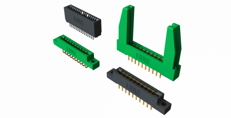
Based on a highly reliable gold-plated, beryllium copper contact system designed to match the 20+ year life spans of SSL products, the 9159 series of two-piece connectors from AVX Interconnect stands out as one of the few exceptions to this rule. The first connector in this series – the 9159 horizontal plug and socket (pictured in Figure 1) – was designed in response to a customer’s request for a coplanar, two-position, SMT, white, connector system that was 50 percent smaller than what was currently available on the market and capable of handling between four and five amps of current. Once that was achieved, the series was extended to include connectors featuring two to six positions to accommodate additional power or mixed power and signal lines and a greater breadth of SSL designs.


Figure 1. AVX’s 9159 series two-piece, coplanar BTB connectors

Over the next couple of years, as customer requests kept rolling in, connector engineers grew more accustomed to accommodating SSL-specific design requirements, and the initial 9159 products began to accumulate years of proven performance, the series continued to expand. First, a straight-cabled plug with an integral latching mechanism that maintains the connection integrity during handling and installation was developed in response to a request for a WTB solution that allowed engineers to build a common board layout with a plug on one end and a socket on the other. Capable of serving either a WTB or BTB function, this plug and socket connector enabled the development of a single board capable of achieving volume economies with almost unlimited expansion based on the required light output.


Figure 2. AVX’s current 9159 Series product offering

Next, a top load socket was developed in response to several customer complaints about board level failures in linear strings, which required technicians to disassemble the light out in the field until the defective board was reached. This solution features a slide-top design that acts a zero insertion force (ZIF) connector and allows one end of an interior board to be quickly and easily lifted up, removed, and replaced in the field, saving both time and money.


Figure 3. AVX’s 9159 series IDC cabled plug and socket connectors and cable assemblies

Later, a vertical connector capable of perpendicular mating was introduced to accommodate linear edge lighting applications while maintaining a common PCB footprint pattern, as with the cabled plug. And, most recently, right angle WTB options in both a plug and socket configuration were introduced to continue the theme of building a single board with a plug on one end and a socket on the other. These two new connectors (Figure 3) allowed for wires to be connected from either side of the board, which effectively simplified applications  in which multiple lights needed to be connected end-to-end to cover a specific distance using standard length lights.

The evolutionary development of the 9159 Series is exemplary of the challenges and innovative solutions that continue to be brought to market by connector manufacturers with the express purpose of satisfying the unique requirements of the rapidly expanding SSL market. Now that a small array of SSL connectors developed by several manufacturers exist, the pace of innovation may not match that of these first few years; however, the continually evolving nature of the SSL industry will surely continue to require novel solutions for new designs.

Categories Blog

The Importance of Fixture Design, Engineering and Thermal Management

According to a recent US Department of Energy (DOE) report, nearly half of all commercial lamps and luminaires sold will be LED-based by 2020.[1]  Additionally, Navigant Research recently released a report stating global unit shipments of LED lamps and luminaires are expected to total 10.7 billion from 2014 through 2023.

While this is excellent news for reducing energy costs and consumption, how does the architectural and engineering community view this technology shift? Are LED luminaire manufacturers able to combine form and function to meet lumen requirements, esthetic specifications, and engineers’ and facility managers’ concerns? The answer is yes if careful analysis and comparison is conducted on the various LED luminaires on the market.

LED Luminaire Form
Often, maximizing lumens per watt takes precedence with manufacturers over luminaires’ complementing architectural schemes. Additionally, meeting the needs of facility managers’ concerns about energy consumption also drives how products are designed and engineered. But, do these have to be mutually exclusive or can manufacturers achieve it all?

Lighting design necessitates an integrated approach—taking into account the exterior conditions, such as exposure to weather and pollution. Both in the dense urban spaces of the cities and in the surroundings of private buildings, the requirements are growing for precision lighting, energy efficiency, and visual comfort.[1]

However, with quality and performance improving, and cost decreasing by about 18 percent each year, LED technology is well positioned for further adoption by the design community for general lighting.

Function and Thermal Management
Are all LED luminaires created equal? Manufacturers have different opinions on how luminaires should be engineered and designed to meet esthetics and function requirements, which involves the overarching issue of thermal management.

Let’s start with a brief overview. LEDs generate heat, but unlike traditional light sources they transmit heat instead of radiating it.  This means most of the heat from an LED goes upward into the fixture housing.  This heat, coupled with heat generated by the power supply, must somehow exit the system through conduction, convection or a combination of both.  Since LEDs are sensitive to heat they must be kept below their rated maximum temperature.  Consequently, luminaire manufacturers need to be conscious of these heat dissipation challenges in order to design effective thermal management systems that support LED performance and longevity.  Inadequate thermal management can lead to a shift in color, lower light output, and dramatically shortened life.

Time and market demand have a way of advancing technology to the point where thermal management may soon be just an afterthought rather than an obstacle in luminaire design. With each generation of LEDs, efficacy continues to rise exponentially; LEDs today are more than 50 per cent efficient—that is, they convert more energy into light than they do into heat.[2]

However, thermal management involves more than just evacuating heat from the fixture; it includes using the best LED and being able to operate at a low drive-current while still providing high lumens per watt. A lower drive-current means less heat, which allows the fixture to manage heat better.

In evaluating manufacturers’ LED luminaires for both form and function, another important issue is the power supply. The type of power supply selected for a lighting application will be based on several factors. First, the environment where the application will be operating in must be considered. For example, is the application for indoor or outdoor use? Does the power supply need to be waterproof or have any special ingress protection (IP) rating? Will the power supply be able to use conduction cooling or only convection cooling?[3]

According to the DOE’s Office of Energy Efficiency and Renewable Energy, the temperature at the junction of the diode determines performance, so heat sinking and air flow must be designed to maintain an acceptable range of operating temperature for both the LEDs and the electronic power supply. Luminaire manufacturers can be asked to provide operating temperature data at a verifiable temperature measurement point on the luminaire, and data explaining how temperature relates to expected light output and lumen maintenance for the specific LEDs used.

Regardless of how efficient LED fixtures are at dissipating heat, ambient operating temperatures still play a major role in a product’s life cycle. Naturally, warmer climates make it harder to maintain the lowest possible operating temperatures during peak summer months. However, cooler geographical areas such as the northern US and Canada have lower temperatures, therefore ensuring a longer LED life:  the cooler the climate the more ideal it is for LED luminaires.

Retrofit Considerations
Many LED retrofit lamps do not retain the exact form factor of their non-LED counterparts. This can lead to challenges with fit, function, and/or thermal management when installed in standard luminaires. Additionally, some LED retrofit lamps’ packaging indicates the lamps are not designed for use in enclosed luminaires such as recessed downlights. If LED retrofit lamps require access to ambient air for thermal management, installing the glass lenses often used with standard luminaires can damage or severely affect the lamp’s performance and life cycle. Also, LED sources can appear extremely bright and/or pixilated and require appropriate shielding and/or cut-off for comfortable application. Unless a manufacturer has optimized the luminaire to account for a specific lamp, performance and appearance may be compromised when LED retrofit lamps are installed.[4]

Conclusion
With the dramatic proliferation of LED luminaire in full force, SSL technology will dominate general illumination going forward. That being said, there are hurdles manufacturers and those specifying LED luminaires must overcome. Specifiers must conduct due diligence on products, particularly because since 2006 there have been 600 new lighting manufacturers in the LED industry.

Designers and specifiers need to play an active role in the development of standards and code requirements to ensure quality lighting is maintained. Beyond important lighting metrics such as efficacy, lumen output, and luminous distribution, designers and specifiers are needed to define the essential attributes of lighting as it becomes integrated with building automation systems, energy management systems, and security systems.[5]

Categories LED

All LED Luminaires Are Not Created Equal

As readers of LED Journal you know that both interior and exterior conventional lighting is rapidly being replaced by LEDs with intelligent lighting management. End-users are reaping the myriad benefits of this technology in reduced energy consumption and costs, and the virtual elimination of lighting maintenance. These benefits provide an incentive to help vigorously drive the ongoing development and implementation of LED technology. However, when considering this technology, it’s important to assess factors that contribute to the lifetime of an LED luminaire.


Kenall's TekDek engineered with a systems-approach. Photo courtesy of Kenall Lighting

Given that the LED luminaire is a system, it is vital to recognize all aspects [of the system] and not just individual components that can affect or limit lifetime. Luminaire manufacturers are learning how to better account for the lifetime behavior of the many components that are used when designing an LED fixture, including drivers, optics, mechanical fixings and housings. Each of these is a factor in determining the lifetime of a luminaire. The primary factors in the lifetime of a LED luminaire are the LED source selection and the durability of the power electronics.

An effective, long-lasting luminaire design combines the most advanced LED sources, driver technologies, optics and form into each product. Let’s examine a few of these components to really get a feel for what engineers need to consider in designing an LED luminaire. The entire luminaire must be built to last for the lifetime of the application.

In the Lighting Industry Liaison Group’s 2011 Guidelines for Specification of LED Lighting, the following criteria provide excellent considerations when determining what factors should be considered for the length of an LED luminaire.

LED Source Selection – When selecting LEDs, it’s important to consider the color, color temperature (if selecting white LEDs), the viewing angle and CRI.  But one of the most important factors is the application: what is the area to be illuminated – spot or area? Optics – diffuser, reflector, lens? Thermal density and heat removal? Size and lit appearance?  Also, does the manufacturer’s LM-80 test data support the lumen depreciation requirement?

Power Electronics’ Durability – The electronics affects almost every performance aspect of an LED design. High quality components – not using electrolytic components when possible and not running at maximum capacity or temperature– help to ensure the luminaire’s reliability and lifetime.

Optical Performance – LEDs are directional light sources, giving the lamp or luminaire designer new challenges when compared to existing lamp technology. The use of reflectors, lenses and diffusers, or a combination thereof, allows a designer to direct light in many different ways. The efficiency of the optical system must be considered and factored into the overall efficiency value of the lamp or luminaire.

PCB – A PCB is the electrical carrier as well as the interface between the LED and heat-sink that carries with it a thermal resistance value. The higher the resistance, the less efficient the system is at wicking away heat from the LED, this may well impact the LED lumen output performance and, ultimately, the life, lumen maintenance and/or catastrophic failure of the LED.

Finish – The paint finish/color may affect the heat dissipation from the luminaire, but more importantly, plays a significant role in the long-term integrity of the luminaire enclosure.  As the finish degrades, the base material of the enclosure may become susceptible to corrosion.  Different applications require different levels of corrosion protection.  Tunnel lighting, for instance, requires one of the highest levels of protection while indoor office lighting, the one of the lowest.

Mechanical – The mechanical integrity of a luminaire is important in several different areas, including: ingress protection ratings suited to the application,  gasketing that will not become compromised with time and/or lack of maintenance, chemical compatibility with all materials used within the luminaire, UV resistance of polymeric materials when used outdoors and vibration resistance.  While solid state lighting sources are inherently vibration resistant, that in itself is not enough to ensure the long term integrity of the remainder of the luminaire, in an application such as street lighting or parking structures, where constant vibration is commonplace.

Thermal Management – The performance of an LED is dependent on its temperature during operation. The design of the luminaire will influence its operating temperature. Heat management is a critical factor that affects LED luminaire performance and the LED lifetime.

Housing – LEDs allow new luminaire design freedom to lighting manufacturers and engineers. Innovative form factors not possible with incumbent lamp sources can be used both for styling and function.  Even though it should be infrequent, design consideration should be given to the maintenance of the LED light source and all power electronics, because even the most well-designed luminaire will eventually no longer meet its expectation of light production.

All LED Luminaires are Not Created Equal – While it’s easy to get caught up in the LED revolution, it’s critical to understand the application as well as manufacturers’ luminaires’ designs. Does screwing in a replacement LED bulb provide the same quality illumination as a well-engineered, from-the-ground-up fixture? As we head into one of the industry’s largest tradeshows, LightFair, take the time to consider the system components I’ve briefly addressed above; these provide metrics for the quality and lifetime of an LED luminaire.

Categories LED

To Ensure Accurate HBLED Testing, Start with the Fundamentals

Ensuring the performance and reliability of HBLEDs demands accurate testing at every phase of production. Many HBLED tests require sourcing a known current and measuring the resulting voltage or vice-versa, so instruments that combine and synchronize these functions, such as source measure unit (SMU) instruments, can speed system setup and enhance throughput. Testing can be done at the die level (both wafer and package), or the module/subassembly level. At the module/subassembly level, HBLEDs are connected in series and/or parallel; therefore, higher currents are typically involved, sometimes up to 50A or more, depending on the application. Some die-level testing can be in the range of 5 to 10 amps, depending on die size.

A forward voltage (VF) test verifies the device’s forward operating voltage. When a forward current is applied to the diode, it begins to conduct. During the initial low current source values, the voltage drop across the diode increases rapidly but levels off as drive currents increase. This region of relatively constant voltage is where the diode normally operates, so this test provides useful information. Results are often used in binning devices because an HBLED’s VF is related to its chromaticity (the quality of color characterized by its dominant or complementary wavelength and purity taken together).

Forward current biasing is also used for optical tests because current flow is closely related to the amount of light an HBLED emits. A photodiode and integrating sphere can be used to capture the emitted photons to measure optical power. This light is converted to a current that’s measured using an ammeter or one channel of an SMU instrument.

A negative bias current applied to an HBLED allows probing for its reverse breakdown voltage (VR). The test current should be set to a level where the measured voltage value no longer increases significantly when current is increased slightly. At higher voltages, large increases in reverse bias current produce insignificant changes in reverse voltage. The VR test is performed by sourcing a low-level reverse bias current for a specified time, then measuring the voltage drop across the HBLED. Results are typically in the tens to hundreds of volts.

In leakage current testing, moderate voltages are normally used to measure the current that leaks across an HBLED when a reverse voltage less than breakdown is applied (IL). In production testing, it’s common practice to ensure only that leakage doesn’t exceed a specified threshold.

Minimizing HBLED Testing Error
Junction self-heating is among the most significant error sources in HBLED production test. As the junction heats over time, the forward voltage drops and the leakage current increases, so it’s crucial to minimize test times. Smart SMU instruments can simplify configuring the device soak time (which allows any circuit capacitance to settle before the measurement begins), as well as the integration time (which defines how long the A-to-D converter acquires the input signal). Some of these instruments, such as the Keithley Model 2651A (Figure 1), have digitizing A-to-D converters, which can sample at speeds up to one million samples per second, which is up to 50 times faster than high-performance integrating A-to-D converters. These higher measurement speeds further improve overall test times.


Figure 1. Model 2651A High Power System SourceMeter instrument.

The use of pulsed measurements minimizes test times and junction self-heating. Modern SMUs with high pulse width resolution ensure precise control over how long power is applied to the device. Pulsed operation also allows these instruments to output current levels well beyond their DC capabilities.

Categories Blog

Card Edge Connectors for SSL Applications

Introduced to the market more than 50 years ago to connect the printed circuit boards of early computer systems together, card edge connectors have remained relevant and continue to be employed in a wide range of modern technology, including solid-state lighting. Originally used to facilitate connections between mother and daughter boards, card edge connectors also established expansion slot standards for PCI, PCI Express, and AGP cards and served as the basis for early consumer video game cartridges. Since then, card edge connectors have evolved to keep pace with the technological developments that have reshaped the electronics industry over the past half-century. Consisting of a single female connector that mates to exposed PCB contact pads processed into the edge of a mating printed circuit board (hence the name), card edge connectors continue to be modified to suit modern applications for three main reasons: simplicity, reliability, and cost effectiveness.

As the electronics industry evolved over the past few decades, card edge connectors were constantly challenged towards higher pin counts and higher signal speeds capable of supporting computer signal level advancements, which was a natural design progression. More recently, however, modern applications like solid-state lighting challenged card edge connectors to provide increased current and voltage levels capable of supporting industrial level performance, the complete opposite of the electrical specifications they were originally designed to provide, so that the rapidly expanding SSL industry could take advantage of the technology’s proven reliability while also making strides toward satisfying cost-competitive consumer product pricing demands. Due to the inherent simplicity of card edge connector designs, these specifications were primarily achieved by altering the contacts, which are the key to any reliable and robust connector system.


Figure 1. AVX 00-9159 Series single piece inverted through board card edge connectors mate perpendicular PCBs to a top-mounted main FR4 or metal core PCB from the bottom side, which is a common configuration in the LED bulb market. Available in two to six positions, they also offer added design functionality, such as color control or specific control lines.

Traditional card edge connectors were made with high spring force contact materials designed to accept multiple mating cycles and compensate for a larger tolerance range of mating PCB thicknesses. Newer card edge connectors designed for use in SSL applications have been developed using beryllium copper (BeCu) contact materials and are often stamped and formed to create the final contact geometry. BeCu has proven to be the best contact material on the market in stamped contacts, providing high spring force without yielding to the elevated temperatures, a large contact deflection range, substantial insertion force tolerance, and long-term reliability. One example of a BeCu card edge connector created specifically for SSL applications is AVX’s 9159 series vertical top and inverse mating connectors for perpendicular applications. Featuring a gold-to-gold active contact mating interface to maximize the mechanical and environmental performance of the connector system, 9159 series connectors provide a minimum of 10 mating cycles while supporting a UL rating of 2A per contact and 300V. Advantages that stamped and formed BeCu card edge connectors like these provide over conventional SMT card edge solutions include: multiple position offerings, up to twice the position density and current capacity, higher voltage ratings, compatibility with several PCB thicknesses, higher maximum operating temperatures, and improved electrical characteristics. Some newer card edge connectors for SSL applications, including the 9159 series, also offer optional versus integrated safety caps to achieve height reductions of up to 33 percent, which makes them much less likely to interfere with light output—a primary concern in SSL designs.


Figure 2. AVX 9159 Series card edge connectors feature gold plated BeCu spring contacts, which provide high spring force without yielding to the elevated temperatures, a large contact deflection range, substantial insertion force tolerance, and long-term reliability.

Other card edge connectors designed for use in SSL applications utilize phosphor bronze contact materials, which are slightly cheaper than BeCu contacts, but have a smaller deflection range. These contacts tend to use edge stamped contact technologies instead of traditional cantilever beam technologies and do not require any secondary forming. Much more rigid than cantilever beam contacts, phosphor bronze edge stamped contacts exhibit a high spring force with a lower spring deflection range, which requires tighter tolerance mating PCBs. Additionally, due to their high force, the number of mating cycles for edge stamped contacts is typically reduced to somewhere around five, or roughly half that of stamped and formed BeCu contacts. Phosphor bronze contacts and edge stamped technology are not new to the interconnect industry. Phosphor bronze is widely used in myriad applications, and edge stamped technology has long been used in FFC/FPC and other card edge configurations. Due to the high/rigid force that these contacts provide, tin plating is often used as a lower cost alternative to the gold plating used for BeCu contacts. The key parameter in any tin-to-tin contact interface is the amount of contact force required to both wipe the contact surface clean during the mating process and to maintain that force throughout the life of the product, which is roughly three to 10 times the force required of a gold interface. One example of card edge connectors that incorporate phosphor bronze contacts and edge stamped technology is AVX’s 70-9159 series coplanar contacts, which is extensively employed in end-to-end strip lighting applications. The UL current ratings for this series range from 2.5 to 3A per contact and 300V depending on the density and pin count of the chosen connector.


Figure 3. AVX 00-9159 open-ended card edge connectors provide higher pin count density and a smaller footprint than existing coplanar board-to-board card edge connectors, reliably connecting two PCBs in a cost effective, assembled solution and enhancing the flexibility with which engineers can mix and match power and signal lines.


Figure 4. AVX’s 00-9159 Series standard board-to-bard card edge connector provides a simple, reliable, and low cost solution for mating PCBs end-to-end in linear SSL strip lighting. The single, stamped contacts have dual contact beams to guarantee high force on standard 1.6mm PCBs and are available in two through five positions on 2mm pitch centers and provide a 3A continuous rating.


In sum, although card edge connectors are one of the more historic connector technologies, their proven simplicity, reliability, and cost effectiveness has encouraged engineers to continually create new card edge connector products designed to meet the performance standards for a variety of modern electronics. Now broadly employed in SSL applications to connect the power and ground signals of LED-to-LED or driver-to-LED boards, a host of proven, reliable, and robust low pin count card edge connectors from a variety of manufacturers are readily available on the market. Standard product sizes typically range from 2p to 6p, and expanded sizes up to 10p, which are ideal for linear lighting applications, are also available from several manufacturers. Further, card edge connectors suited for both metal core and FR4 PCBs, which are growing in SSL popularity due to the fact that newer LEDs consume less power and generate less heat for the same light output than they did even just a few years ago, and widely available as well.

Categories Lighting

LED Lights Will Help Reduce Blackouts this Summer

Blackouts suck! It is one thing if a storm knocks out power when a tree blows over electricity cables. On the east coast, I have experienced power loss one or more times each winter at our home outside of Philadelphia, but the power is typically restored within a few hours or a day, subject to the level of damage.

Waiting to replace traditional commercial lights with energy-efficient LEDs may now become more of a collective call to action than an individual business decision based on Return on Investment. To date businesses have evaluated the savings opportunities with commercial LED lights relative to their own financial situation. Investing $100,000 may save $33,000 or more each year, which yields a favorable 33 percent or greater ROI and paybacks in three years or less. The disruptive LED technology has not been adopted in America at the levels of other countries in Europe and Asia, in part because our US cost of energy is less expensive than in many other countries.

Now, states like California are literally reaching capacity on their power supply relative to demand. Over the summer, when peak loads are at the highest, given the combination of air conditioning and the lights at homes and offices, the power situation is becoming dire. The summer afternoons create the most risk, because the electricity consumption is high at both homes and offices when some employees head to their residences where they proceed to turn on lights, air conditioning, TVs, etc. This added demand will shut down the grid for more than just the time it takes to chain saw a tree off of an east coast fallen power line. Some insiders predict that blackouts could last for multiple days or longer.

We collectively have an opportunity to accelerate energy intelligence to reduce the risk of blackouts by changing our lights. What is good for the grid is also good for each business and the planet.

With 1.341 lbs of CO2 emissions reduced for every kWh saved, changing the lights to LEDs never looked brighter and more responsible, when it comes to environmental stewardship.

For companies that do not have funds budgeted some LED lighting manufacturers, like Independence LED offer $0 upfront cost financing with cash-flow positive results from the start. The financing programs provide business owners with the opportunity to act now vs wait until the less efficient existing lights go out, or the building goes dark in a black out. Saving 50 percent or more on the energy consumption for each commercial building aggregates into a massive positive impact since over 20 percent of US building energy is typically used in the ceiling for illumination. Buildings overall account for about 40 percent of US energy consumption, so changing the lights makes sense on many levels.

Here is some support information from ABC News on March 19th.

“For the first time since January, rolling blackouts were ordered in California today, turning out the lights in approximately 500,000 homes, including some in Beverly Hills.

Officials at California’s Independent System Operator (ISO), which monitors the state’s power grid, called a Stage Three alert at midday because of increased temperatures, a higher power demand and a lack of electricity from the Northwest.

Further complicating the situation was the closure of two power plants.”

As the general election of the presidential race heats up, we’ll see if either Donald Trump or Hillary Clinton address electricity demand and call for Americans to look up at their ceilings and seriously consider changing their lights to LEDs.

Categories Lighting

Standardization and Testing of LED Light Sources for the Sake of Interchangeability

The Zhaga consortium is a global cooperation among lighting companies. Their objective is to develop specifications that can enable interchangeability of LED light sources made by different manufacturers.

Zhaga intends to develop specifications for LED light sources that can be used globally in a wide range of general lighting applications. The consortium has adopted a collaborative standardization approach, and for the past three years it has been holding frequent meetings around the globe to facilitate member participation and rapid development of these specifications.

Each Zhaga specification is called a “Book”. The process of developing a book begins with one or more member companies proposing an LED light source, intended for a specific application or with particular features, that they would like to see standardized for interchangeability. Technical Input from member companies is then collected and merged into a common design proposal for interchangeability. From that point, requirements can begin to be written and prototypes are built as part of the specification development. The process ends with the approval of a new specification by the consortium members and each new specification is assigned a unique “Book” number (e.g. Book 2, Book 3, etc.). This whole process is repeated for each new LED light source that is proposed for interchangeability standardization.

For the purpose of Zhaga, an LED light source is always considered to be the combination of an LED module (or modules) and its associated LED driver (aka electronic control gear) and is referred to as an “LED light engine” (LLE). Depending on whether the LED driver shares a common housing with the module or if the driver is provided in a housing independent from the module, the LLE may be categorized as “Integrated ECG type” or “Separate ECG type” respectively. For this reason, Zhaga Books address the interchangeability of the complete LLE in a luminaire from a system approach.

To date Zhaga has developed seven specifications. LLE configurations include both integrated and separate LED driver designs. Additionally, some of the LLE configurations are intended to be interchangeable without the use of a tool “socketable type” and some are intended be factory installed and serviced by qualified personnel. These LLEs are suitable for a variety of applications including recessed downlight, track light, spotlight and high bay. This is already an impressive collection of Books developed over three years, but considering that LEDs are increasingly being used in new applications, there is room for many more specifications to be created. Companies interested in proposing new LLE types for Zhaga specification should consider joining the consortium and participate in the definition of new books.


Figure 1. Seven Books developed for product certification

Each Zhaga Book defines interface requirements for a different type of LED Light Engine (LLE). The books only define the minimum requirements that are necessary to achieve interchangeability. The specific LED chip or array used inside the light engine is not controlled by Zhaga specifications and can continue to evolve. This approach makes it easy for “Zhaga” LLEs to adopt increasingly better performing LED components while retaining interchangeability; a concept Zhaga refers to as “future-proof”.


Figure 2. Zhaga interfaces

Interchangeability of two different light engines in a luminaire implies that both light engines are compatible with the luminaire and provide comparable user experience. To that end, Zhaga has identified 5 interfaces that are sufficient to specify interchangeability requirements.

The first three interfaces (mechanical, electrical and thermal) are essential to determining an LLE can fit and operate properly in a given luminaire. The other two interfaces (photometric and control) are needed to help the users determine if two LLEs built by different manufacturers can deliver comparable lighting experience. Each interface is characterized by certain parameters that can be verified through testing.

For the most part Zhaga interfaces relate to intuitive and common parameters that are applicable to conventional lighting products. The mechanical interface may specify dimensions or fit codes that can be verified using measuring instruments or gauges. The electrical and control interfaces are characterized by operating voltage, power ratings and dimming technology that can be verified using standard electrical laboratory instruments.

The photometric and thermal interfaces on the other end involve some unique features and require specialized testing (instrumentation, environment and fixtures). This is partly due to the fact that photometric performance of LEDs requires tight thermal controls.


Figure 3. Luminance picture illustrating how a rectangular light emitting surface can be divided into eight segments for analysis.

The photometric interface is typically specified by light intensity (luminous flux) and color (CCT, CRI) parameters as measured under specific thermal operating conditions. Depending on the book, the photometric interface may also involve parameters to help specify luminaire optics that can be used in combination with a light engine. These may include the position, dimension and location of the light emitting surface, or near field luminance properties as measured by a CCD camera.

The thermal interface is based on model which assumes that the bulk (~ 90 percent) of the heat generated by a Zhaga LLE is dissipated across a surface designed to be in contact with an external heatsink. This portion of the total thermal power (Pth) dissipated by the LLE is referred to as thermal power rear (Pth, rear) and is measured using a heat transducer equipment specially designed for this purpose.

Zhaga administers a testing and logo program that allows members to identify and promote products that comply with the specifications. These products are registered in the Zhaga on-line product directory and are eligible to bear the Zhaga logo.

Zhaga will certify products that have been tested by an Authorized Test Lab and have been determined to be compliant with the requirements of related Zhaga Book. Authorized Test labs are testing companies that are members of the Consortium that have met objective criteria to demonstrate they can perform all the tests in a Zhaga book.

UL is among the first test labs to become authorized to perform certification testing for Zhaga books.  UL currently offers global capability, expertise, evaluations and compliance testing services to assist companies interested in developing Zhaga light engines, luminaires and components. Zhaga testing is available separately or as a bundle along with other UL lighting industry services such as Energy Star, Photometric performance testing and/ or Safety Certification (per US, Canada and IEC standards).

Safety is evolving. So is UL. With innovations that have established a benchmark of trust worldwide for more than 118 years, UL looks forward to advancing its ongoing efforts to more safely and efficiently deliver LED interchangeable products to the marketplace. Visit us on the web, www.ul.comzhaga.

Categories Product

Fundamentals of the IoT: What is Driving Next-Generation Products?

The early adoption of the Internet of Things (IoT) is proof that a completely connected universe will be a reality in the not so distant future. Soon enough, our garage door opener will communicate with the lights inside our homes and our coffee makers will be linked to our iPhone alarms. Everything will be controlled from the devices in our pockets and the wearables on our wrists. 

In general, as consumers, we focus mainly on the end product – the benefits or entertainment it delivers, what is different, how it has improved, or how it makes our lives easier. We rarely stop to think about what is actually enabling these advancements.

A recent Deloitte Global and US Council on Competitiveness study identifies 10 of the most promising innovations and why they are important. Among them are IoT, predictive analytics, smart factories, and high-performance computing. What may surprise most consumers is that advanced materials also ranked high on the list.  The importance of advanced materials is common knowledge among the leading companies that develop and manufacture next generation products.  In fact, advancements in materials technology have been the genesis for all of the computing devices that have become critical to our daily lives.  Developing the next generation of advanced materials starts at the molecular/atomic scale where properties can be amplified and fine-tuned. The most powerful of these advanced materials are referred to as nanomaterials.  These nanomaterials can be used to deliver applications ranging from revolutionary drug delivery to dramatically more efficient lighting to mobile devices that help to manage our world.  The cumulative effect of advanced materials innovation has been to deliver a vast array of transformational products that continue to improve the human experience. 

How are the leading manufacturers across numerous industries leveraging these advanced materials to deliver breakthroughs in medicine, lighting, cars and iPads? How are they constantly improving on these innovations? And how do they fit into the IoT landscape?

Simply answered, they partner with the leading companies that are delivering the biggest advancements in nanomaterial technology, making the largest investments in materials R&D, and finding ways to deliver solutions at commercial scale.  The leading electronics manufacturers (Apple, LG, Samsung, etc.) are fiercely competing to deliver faster processors, brighter lights, thinner devices and more flexible screens that their customers are continually demanding.  Advanced materials manufacturers enable these companies to create revolutionary products at an ever-accelerating pace, while at the same time reducing costs, time to market, and their environmental footprint.

What makes one type of material better than the other? It’s all about the process.  Advanced materials manufacturers need to perfect their processes in order to provide the control and flexibility demanded by their customers. In applications such as lighting, for instance, they need products that deliver more light output, with near perfect transparency, that have a long life time. Our company, Pixelligent, has found a way to create such an environment through delivering next generation, nanotechnology-based solutions at commercial pricing and scale. Our “secret sauce” – the PixClearProcess – ensures that consumer products that incorporate our technology are higher quality and more efficient. What was once a distant nanotechnology future is now a reality: a set of highly valuable advanced materials that can be delivered in meaningful volumes with the right value proposition to the commercial marketplace.

Almost every chemical and manufacturing company you can name is using advanced materials to drive their products forward and offer more innovative options to their customers. Today, three of the five largest global chemical companies are working with Pixelligent, and several of the top 50 advanced materials companies are our customers.

Stay tuned for my next blog post, which takes a deeper look at how advanced materials and nanotechnology is driving innovation and efficiency in the lighting industry.

Categories Lighting

High Marks for High School Lighting

With over 350 schools, covering more than 24 million square feet, the Clark County School District (CCSD) is the fifth largest and fastest growing school district in the US. CCSD’s Facilities Division is one of the most comprehensive, sophisticated, and sustainable design-oriented districts in the country. They are in the process of designing and building over 100 new schools to meet the tremendous growth of the greater Las Vegas metro area. All of the new schools will be LEED Gold Certified.

Ed W. Clark High School – Las Vegas, NV
In addition to this new construction, the district is implementing extensive renovation and modernization at existing facilities such as Ed W. Clark High School. Built in 1964, the high school serves grades 9-12 and approximately 2,070 students. Steve Johnston, CCSD design manager for the Clark High School modernization project, is overseeing the ongoing $30 million renovation that includes HVAC and plumbing upgrades, improvements to the locker rooms, food service kitchen, science labs, the fire/sprinkler system, and technology advances such as LAN and classroom projector installations, as well as daylighting in the student activity center. Additionally, because of a federal grant, Johnston looked to upgrade the inadequate and outdated exterior lighting system.

Working with Johnston on this renovation was Jeff Iverson from TJK Consulting Engineers. Wanting to reduce energy consumption and costs Johnston and Iverson looked into LED luminaires and did a comparison with other lighting technology – there’s no comparison regarding the efficiency or quality of illumination. Previously, the school had 91, 70-watt high intensity discharge fixtures installed around the school in overhangs and doorways. In a one-for-one replacement, the school now has 91, 23.1-watt LED canopy and wall-mounted exterior luminaires, almost a full replacement of exterior luminaires on the school grounds. This LED installation is reducing the school district’s energy consumption by 75-percent over the incumbent fixtures.

“We sought to install a one-for-one replacement that would increase visibility and outlast the old HID lighting that was costly to maintain. We’re expecting to save a lot of time and expense in maintenance,” said Johnston.

Providing a safely illuminated campus during evening hours was also an important reason for selecting new lighting. Johnston and his colleagues are very pleased with the vastly improved lighting quality and uniform lighting performance from the LED luminaires.

Reduced luminaire maintenance is a benefit welcomed by Jack Viscosi, Clark County School District electrical/mechanical repair coordinator, who’s responsible for the electrical maintenance at Clark High School. LED luminaires are designed to provide a virtually maintenance-free operation for more than 15 years in the harshest outdoor environments while HID last only two to three years.

This is the school district’s first LED luminaire installation but it won’t be the last. A commitment to reducing energy consumption and environmental stewardship will help facilitate additional sustainable projects as funds become available.

The $30 million renovation is funded largely through a 1998 voter approved bond fund, and federal grants specifically for the lighting upgrade as well as a solar thermal grant for the installation of an adsorption chiller in the central plant that controls the school’s cooling.

According to the US Department of Energy, energy-efficient renovations—replacement of inefficient boilers, lighting, and other systems—could reduce school energy costs by 30 percent. This is money that could be spent on hiring new teachers and purchasing textbooks, computers, and other instructional materials.

Categories LED

Testing High Power LEDs? Watch Out for Inrush Current!

As an instrument applications engineer, I talk to a lot of design engineers who work with high power LEDs. All too often, they overlook the risk of inrush current, which they can apply inadvertently during testing. This post explains what happens, why it’s a problem, and how to prevent it. First, let’s review a few basics.


Figure 1. Typical I-V curve of a diode.

An LED is a two-terminal semiconductor device. A diode turns ‘on’ at a characteristic voltage (Vd) in the forward bias operating region when an avalanche of electrons and electron holes start to recombine. During this recombination process, one of the properties of an LED is the release of energy in the form of photons, which cause the LED to illuminate. The I-V characteristic of a diode in the forward bias region is depicted in Figure 1, where Vd is the on-voltage of the diode.

Although LEDs can be driven with either voltage or current, current is the preferred method because LED brightness is proportional to its drive current. As the I-V curve in Figure 1 indicates, a small change in voltage results in large variations in current, which will lead to drastic and undesirable variations in LED brightness. In addition, temperature and aging can cause Vd to drift over time. Again, this small voltage drift will likely cause unwanted current variations. Furthermore, driving LEDs with excessive amounts of current can result in irreversible damage and lead to much shorter device lifetimes. Therefore, regulating the drive current at appropriate levels in LEDs is critical.


Figure 2. Test system schematic.

Inrush current is a common phenomenon that overstresses LEDs. An LED can be modeled as a parallel R-C network; as a result, the device is instantaneously a short circuit when a voltage is applied across the device’s terminals. This instantaneous short circuit results in an inrush current, a short-duration startup current, that is of a much greater magnitude than the LED’s steady state operating current. For example, introducing an LED to an energized circuit or “hot switching” the LED may lead to an inrush currents of damaging magnitude. Figure 2 shows that when the switch is open, the voltage at the power supply is maintained at the rated voltage of the LED. As soon as the switch closes, the charge stored at the output of the power supply and the wires flows rapidly into the LED until the power supply starts to regulate. The transient current peak is shown by the blue line in the oscilloscope view in Figure 3(a).


Figure 3. LED turn on voltage (yellow) and current (blue) waveforms when powered by a power supply in the traditional constant voltage (CV) mode (Figure 3a) and the constant current (CC) mode (Figure 3b).

When testing LED designs, engineers typically use a benchtop power supply to drive power to the device precisely while they are taking measurements. Too often, engineers have the settings wrong or they use a power supply that isn’t fully controllable, and end up destroying their devices. But this doesn’t have to happen to you.

A growing trend in power supply design is the addition of a constant current (CC) mode beyond the traditional programmable constant voltage (CV) mode. When a supply operates in the CV mode (Figure 3a), the voltage is regulated while the current may vary. Unlike traditional powers supplies, this new breed of power supplies can be put in a constant current mode independent of the load value. This results in the behavior captured on the oscilloscope in Figure 3b. When the power supply is operating in the CC mode, the current is regulated and supplied to the load while the voltage output may vary. This mode eliminates the need for external controlling circuitry and simplifies the approach to “soft start” a LED. The power supply itself is capable of keeping the current input to the LED under control until the LED reaches the ON-voltage. Removing the possibility of transient inrush current protects the LED from related damage.