As an instrument applications engineer, I talk to a lot of design engineers who work with high power LEDs. All too often, they overlook the risk of inrush current, which they can apply inadvertently during testing. This post explains what happens, why it’s a problem, and how to prevent it. First, let’s review a few basics.
Figure 1. Typical I-V curve of a diode.
An LED is a two-terminal semiconductor device. A diode turns ‘on’ at a characteristic voltage (Vd) in the forward bias operating region when an avalanche of electrons and electron holes start to recombine. During this recombination process, one of the properties of an LED is the release of energy in the form of photons, which cause the LED to illuminate. The I-V characteristic of a diode in the forward bias region is depicted in Figure 1, where Vd is the on-voltage of the diode.
Although LEDs can be driven with either voltage or current, current is the preferred method because LED brightness is proportional to its drive current. As the I-V curve in Figure 1 indicates, a small change in voltage results in large variations in current, which will lead to drastic and undesirable variations in LED brightness. In addition, temperature and aging can cause Vd to drift over time. Again, this small voltage drift will likely cause unwanted current variations. Furthermore, driving LEDs with excessive amounts of current can result in irreversible damage and lead to much shorter device lifetimes. Therefore, regulating the drive current at appropriate levels in LEDs is critical.
Figure 2. Test system schematic.
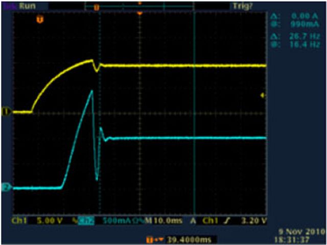
Inrush current is a common phenomenon that overstresses LEDs. An LED can be modeled as a parallel R-C network; as a result, the device is instantaneously a short circuit when a voltage is applied across the device’s terminals. This instantaneous short circuit results in an inrush current, a short-duration startup current, that is of a much greater magnitude than the LED’s steady state operating current. For example, introducing an LED to an energized circuit or “hot switching” the LED may lead to an inrush currents of damaging magnitude. Figure 2 shows that when the switch is open, the voltage at the power supply is maintained at the rated voltage of the LED. As soon as the switch closes, the charge stored at the output of the power supply and the wires flows rapidly into the LED until the power supply starts to regulate. The transient current peak is shown by the blue line in the oscilloscope view in Figure 3(a).
Figure 3. LED turn on voltage (yellow) and current (blue) waveforms when powered by a power supply in the traditional constant voltage (CV) mode (Figure 3a) and the constant current (CC) mode (Figure 3b).
When testing LED designs, engineers typically use a benchtop power supply to drive power to the device precisely while they are taking measurements. Too often, engineers have the settings wrong or they use a power supply that isn’t fully controllable, and end up destroying their devices. But this doesn’t have to happen to you.
A growing trend in power supply design is the addition of a constant current (CC) mode beyond the traditional programmable constant voltage (CV) mode. When a supply operates in the CV mode (Figure 3a), the voltage is regulated while the current may vary. Unlike traditional powers supplies, this new breed of power supplies can be put in a constant current mode independent of the load value. This results in the behavior captured on the oscilloscope in Figure 3b. When the power supply is operating in the CC mode, the current is regulated and supplied to the load while the voltage output may vary. This mode eliminates the need for external controlling circuitry and simplifies the approach to “soft start” a LED. The power supply itself is capable of keeping the current input to the LED under control until the LED reaches the ON-voltage. Removing the possibility of transient inrush current protects the LED from related damage.
