The California Energy Commission (CEC) in conjunction with the California Public Utilities Commission (CPUC) drafted and adopted a document for a new California Quality Lamp, which is currently voluntary. However, beginning in 2014, only LED replacement lamps that meet this new specification will be eligible for rebates in the state. The rationale and drive behind the new specification is to promote quality of light over cheaper, poorer LED replacement lamps that may negatively impact consumer adoption of high efficiency LED light sources.
Development of the new spec was fueled by the historic low adoption rate of poor quality CFL bulbs, which began flooding the market in the 90s when China ramped up mass production of the helical CFL design. Utilities, wanting to reduce energy consumption due to rising oil costs and global warming, encouraged residential consumers to swap out incandescent lamps for CFLs through rebates and buy-downs. Unfortunately, the ultimate market penetration of the CFL was extremely low (roughly 11 percent nationally and 20 percent in California) due to the performance and perceived value of the CFL. Noticeable flaws in CFLs were poor quality of light, the inability to dim, the short life, the flicker, the buzz, the shape, the slow start up in cold weather and the mercury content. This overall lack in comparable product performance drove the consumer back to incandescent bulbs as the primary choice on the basis of both price and quality.
In a nutshell, the perfect storm of events occurred in the US lighting industry demonstrating the importance of all Four P’s of the ‘marketing mix’ – product, price, promotion and place. The results have created a long lasting negative view of CFLs despite significant product improvements in almost all attributes.
The introduction of the California Quality Lamp is positioned by the CEC and CPUC to be the game changer in product performance for energy efficient replacement lamps. Key lessons were learned from the failed CFL marketing approach and, as a result, the voluntary CEC spec focuses primarily on LED light quality, dimmability and longevity while adopting Energy Star performance criteria in other areas such as efficacy. The CEC allows only omnidirectional, floodlamps and spotlights to be qualified as California Quality (refer to summary table of select criteria below).
Product performance is but one of the Four P’s of the traditional marketing mix and understandably, the CEC cannot alone significantly impact the other three factors of price, promotion or the place of sale/method of distribution. So how will the California Quality Lamp succeed and what is the broader plan?
The white paper, “Relighting American Homes with LEDs”, and the DOE study on ‘Lessons Learned’ as cited in Appendix D of the Voluntary California Quality LED Lamp Specification, certainly seem to point toward a more consumer-oriented niche marketing program, collectively known as the Four C’s.
- Understand and focus on what the Consumer needs rather than the product alone
- Shift from price to Cost of ownership, i.e. long term value
- Replace promotion with Communication which includes emphasis on education, environmental impact, advertising and incorporate use of social networks
- The place and method of distribution should offer Convenience utilizing channels such as the internet and other trends in purchasing
You have the hindsight and the foresight to make the light right! Good luck California, and as always, you lead the way.
Summary of Select Residential California Quality Lamp requirements vs. Energy Star Requirements
| Performance Criteria | California Quality Lamp | Energy Star Lamps |
| Lamp base and Lamp Shape | Limited to Omnidirectional, spotlight and newly defined flood lamps | Open to more bases, shapes and decorative lamps |
| Efficacy | Not required | Between 40 – 50 lumens/Watt depending on lamp type |
| Light Output at Elevated Temps | Not Required | 90% or greater output at elevated temperature |
| Correlated Color Temp – CCT | Only 2700K and 3000K | 2700K, 3000K, 3500K, 4000/4100K and 5000K |
| Color Rendering Index – CRI | CRI ≥90 and R9=.50 | CRI≥80 and R9=0 |
| Dimming, noise, flicker | 100% – 10%, free of noise and flicker | No established criteria |
| Lumen Maintenance | Not Required | Shall maintain ≥80% of output at 40% of rated life |
| Rated Life | Same as Energy Star | Not less than 25,000 hours for residential lamps |
| Power Factor | Pf ≥.9 | Pf ≥.7 |
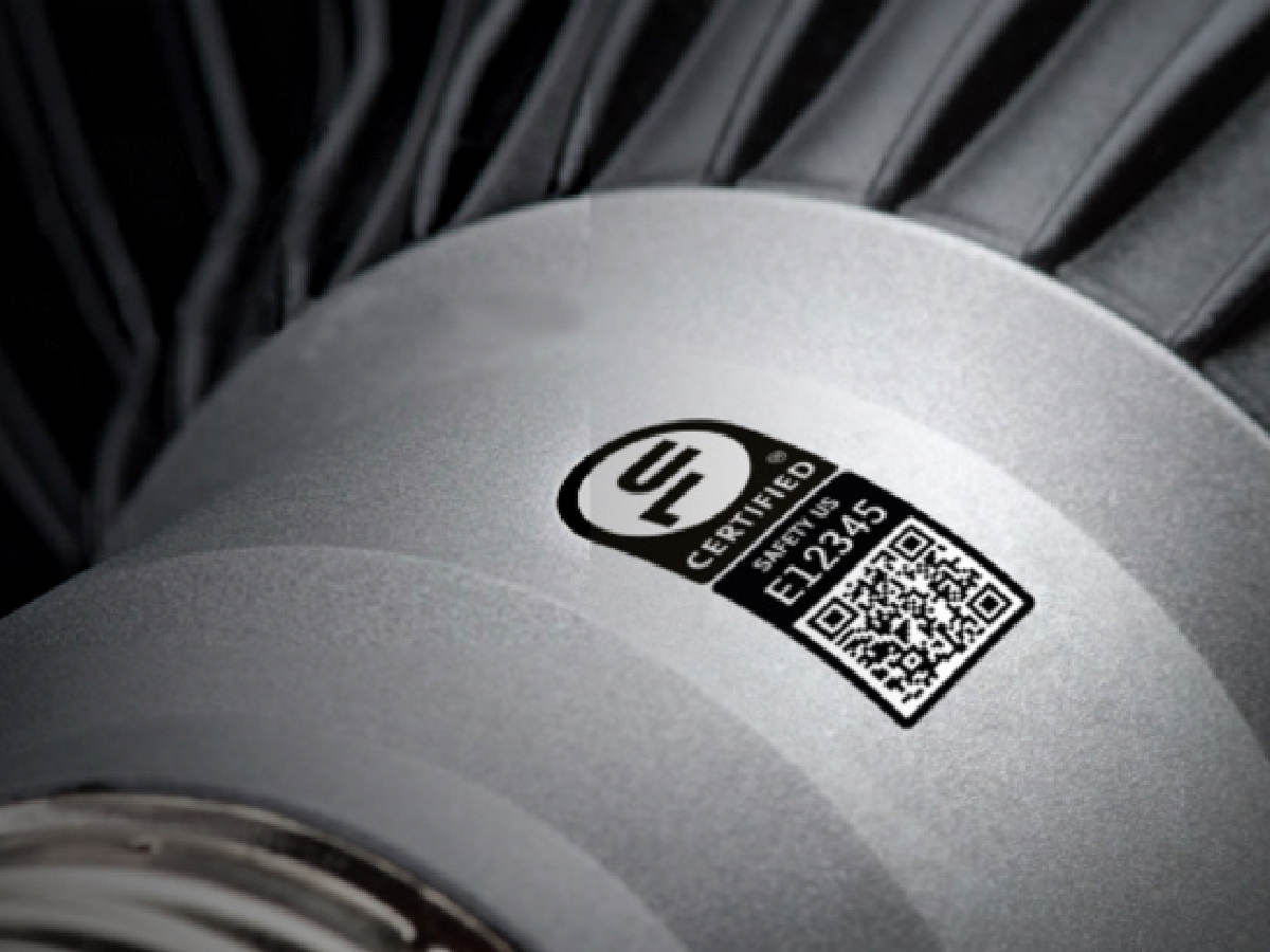
| Electrical Safety | Not Required | Must Comply with UL1993 and UL8750 |
| Warranty | Minimum 5 year Warranty | Provide a Warranty period (not specified) and contact information for manufacturer |