Categories Lighting

Global LED Lighting Trends Reveal Significant Growth and Product Development

The outlook for the LED lighting market remains very bright. Despite fluctuations in the economy and the general lighting industry, LED lighting continues to occupy a significant portion of the overall lighting market. In fact, a November 2014 article in LEDinside, a research division of TrendForce, has projected that LED lighting market penetration will reach 31 percent of the $82.1 billion global lighting market in 2015. LEDinside also reported that Europe is the largest geographic market segment—accounting for 23 percent of the global lighting market share, followed by China at 21 percent and the US at 19 percent. Industry analysts predict significant growth over the next decade.

Product development managers and electronics engineers in the LED lighting market strive to continue growing right along with the industry trends. To succeed in developing LED designs that flourish in the current market, however, they must incorporate reliable circuit protection technologies that deliver a strong return on investment (ROI).

This LED market report reveals the present state of the market, trends for several LED segments and projections for global growth. It highlights the need for industry-leading circuit protection solutions from a reliable manufacturer and specifies the ideal protection devices for several LED applications.

Present State: LED Market is Shining Bright
Recent statistical data supports the pivotal position of LED technology in the global lighting market. Global LED lighting market penetration is expected to reach 31 percent in 2015, according to a recent article from LEDinside. In addition, LEDinside has reported that the global commercial LED lighting sector will reach $26.7 billion in 2015.

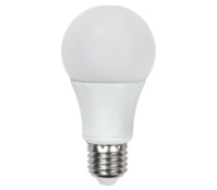
Some of the most common applications for LED lighting are outdoor, residential and architectural. Outdoor LED lighting is quickly gaining popularity for tunnels, roadways, traffic lights, parking lots and garages. According to Strategies Unlimited, 2013 revenues for outdoor LED lighting were $0.7 billion. The firm also reported that nearly two million LED luminaires were installed in tunnels and roadways in 2012. IHS Technology stated that out of the 140 million streetlights installed worldwide in 2013, 19 million of them were LEDs (Source: Forbes).

Residential applications for LEDs include lighting in kitchens, hallways, dining rooms and bathrooms. When compared with other lighting technologies, only LED lighting can be used as a comprehensive replacement for fluorescent lighting (Source: LEDinside). LEDs can be used in multiple rooms throughout the home, are available in several varieties and offer a technology that is relatively easy for consumers to learn. McKinsey’s 2012 lighting market report revealed that residential is the largest general application segment for LED lighting. In 2011, it represented almost 40 percent of the general lighting market.

According to MarketWatch, the architectural segment is the second-largest end-user segment for LED lighting. For architectural applications, LEDs are used in both decorative and functional lighting. Decorative LEDs are used to illuminate fountains, pools, gardens and statues. For functional applications, including building facades and landscaping, LEDs provide visibility and enhance safety on residential and commercial properties.

In response to the current LED market trends, manufacturers are making significant changes in their operations. IHS reported that manufacturers are placing a greater emphasis on vertical integration, focusing on chip-on-board modules and light engines in 2015. Moving down the supply value chain to products that form the intermediate steps between LED components and lamps/luminaires may be an attractive strategy due to the low-profit margins for LED components. Both Phillips and Siemens, top players in the LED lighting market, have separated their lighting work from their core business to enable faster response-to-market dynamics and to achieve higher profitability. In addition, GE has taken steps to start producing its own LED circuit boards and may spin off its lighting business in the future.

Future Promise: LEDs Light the Way to Outstanding Growth
Forbes has predicted that the LED market will continue to grow throughout the next decade, with the global LED market share reaching about 70 percent by 2020. According to McKinsey, Asia will occupy about 45 percent of the global general lighting market by 2020. The report indicated that rapid penetration in Japan and China is driving Asia’s market-leading position for transitioning to LEDs in general lighting. In Europe, the current LED value-based market share is approximately 9 percent, McKinsey reported. By 2020, the share is expected to rise to over 70 percent.


Figure 1. The global growth of the outdoor LED market is self-evident as cities around the world adopt LED lighting. London (pictured above) announced the largest street modernization project with plans to replace 350,000 of the 520,000 city streetlights with LED lights by 2016.

Outstanding growth is projected across various LED market segments, including residential and architectural. Forecasts for LED growth in the residential segment are almost 50 percent for 2016 and over 70 percent for 2020, according to McKinsey. For architectural lighting, MarketWatch revealed that Japan and Europe are the fastest-growing regions. McKinsey has predicted that architectural lighting will remain the early adopter for LED lighting, with its market share reaching almost 90 percent by 2020.

The outdoor lighting industry is also expected to grow at a rapid rate. Strategies Unlimited has forecast that the global outdoor LED lighting market will reach $1.9 billion by 2017. The organization has also predicted that LED street light installations will grow by 400 percent over the next five years. According to Semiconductor Today, the market share of LEDs in street lighting worldwide will grow from 53.3 percent in 2014 to 93.8 percent in 2023.

Safeguard ROI: Circuit Protection for LED Lighting Innovation
Electronics engineers and product development managers are continually innovating LED designs to keep pace with the latest market trends. Creating designs for LED lighting applications presents several challenges, including the need to protect the LEDs’ electronics and circuits from lightning, transient surges and electrostatic discharge (ESD). These electrical threats may jeopardize the safety of personnel and endanger the consumer’s ROI. Failure to use proper safeguards could also lead to compliance issues with regulatory and safety standards related to overvoltage transients.


Figure 2. Outdoor lighting applications have a much better chance of delivering their full ROI with the proper implementation of surge protection devices (SPD) such as the LSP05-LSP10 Series from Littelfuse.

Circuit protection technologies are vital for safeguarding the vulnerable electronics and circuits within LEDs. To prevent LED lighting from experiencing failures within an investment payback period of about five years, high durability and reliability are essential. Before selecting a compatible circuit protection device, it is important to find a manufacturer who understands LED lighting industry standards and the safety issues associated with designing LED retrofit lamps and outdoor luminaires.

As the global leader in circuit protection, Littelfuse recommends protection devices for LED driver and power converter circuits used in a variety of lighting applications. Littelfuse manufactures a variety of fuses, varistors, surge protection modules (combination of varistors) and TVS diodes for LED lighting applications. To ensure compliance with industry standards and reliability, the company performs extensive product testing.

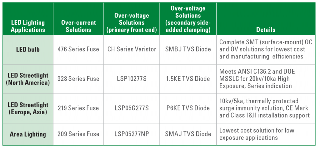
The following table indicates the ideal circuit protection device for several applications:


Table 1. Circuit protection solutions for LED lighting applications.

Conclusion
According to industry experts, the global LED market is experiencing rapid growth across several applications and will continue to grow throughout the next decade. In response to this growth, the demand for high-reliability circuit protection technologies will continue to increase. Circuit protection is needed to safeguard sensitive LED electronics and circuits from electrical threats and meet industry standards for safety and reliability. This technology also prevents LED lighting from experiencing failures within an investment payback period of five years. Fuses, varistors, surge protection modules and TVS diodes are designed to protect LED applications and maximize the lighting investment.

Categories LED

Diving into Benefits with LED Luminaires in Natatorium

Pool Lighting – Indoor pools are hard on light fixtures. The exposure to a warm and humid environment is particularly challenging. Additionally, because natatorium fixtures are difficult to access, maintenance must be kept to a minimum.  If any fixture’s or lamp’s glass were to fall into the pool during maintenance, the entire pool needs to be drained – an expensive and time-consuming effort.

Life safety and accident prevention are the driving forces behind natatorium lighting. Because water is a reflector, reducing the glare from the fixtures is critical.  Adequate light levels, bright illumination, and consistent uniformity are also very important.

Fixtures for this application need to be at least damp location rated, offering the highest safeguard against moisture and water treatment chemical vapors. 

One way to address all of these issues is through the installation of LED luminaires.


Waukesha South High School Natatorium | Waukesha, WI
South High School is Waukesha’s oldest high school, opening in 1957. Today, the 1,460 students use a swimming pool complex that was rebuilt in 2005, replacing a smaller and much older pool, spectator and locker room facility. The current natatorium is larger than in most schools, measuring 25 yards x 30 meters and the oversized perimeter accommodates nearly 2,000 spectators.

The 27,000 square-foot natatorium is used extensively by the high school physical education department, the school’s swim team and the Waukesha Express Swim Team.

Lighting – The complex was originally designed with a metal halide (MH) indirect lighting system to reflect light from the ceiling to minimize glare on the water’s surface. Over the years the ceiling and walls darkened due to deteriorating light levels and fixtures burning out, creating a cave- and dungeon-like atmosphere. Replacing the burned out fixtures was so challenging, they were typically left until there were enough to warrant bringing out the lift.

Tom Cherone, master electrician Waukesha School District, knew the lighting system needed improving:

  • spectators were complaining they couldn’t see the swimmers because the lights were so dim;
  • the low light levels were a safety issue for the lifeguards;
  • he was worried while conducting maintenance on the MH fixtures that if glass dropped and broke in the pool the 480,000 gallons of water would need to be drained;
  • and MH technology requires 10-15 minutes of “cool down to relight,” meaning that the bulbs needed to cool down enough before they could be re-lit again, which was very inconvenient.

Through Wisconsin-based Hein Electric Supply, which has a long-time relationship with Waukesha School District, Cherone learned about retrofitting the existing lighting system with LED high bay luminaires to improve illumination quality, safety and security while also reducing energy costs and consumption.
Recently, in a one-for-one replacement, 42, 1000-watt MH fixtures were replaced with 240-watt LED high bay luminaires and eight, 36-watt florescent tubes were retrofit with 80-watt LED high bay luminaires.

“The new lights are terrific,” said Cherone.  “They strike instantly, provide more lumens than our old MH lights, will last for years and are cost effective.”  “When all the fixtures are on we’re saving an astounding 70 percent in energy over the previous MH lights,” Cherone continued.

Because they emit far less heat than MH fixtures, the school will be able to run the air conditioning less in the summer months, further reducing the energy bill.

Additional power savings are achieved from turning off the fixtures when not in use. The previous lights were left on continuously because they took so long to warm up to full brightness.  These LED luminaires light immediately, eliminating the need to have them on all the time.

“At swim meets I used to apologize to the visiting teams because it was so dark,” said Blaine Carlson, CEO/head coach Waukesha Express Swim Team. “Now, with these new lights, I think we can even attract additional meets to this facility,” Carlson continued.

Cherone is so pleased with the reduction in maintenance, energy savings and consumption, and the dramatic improvement in light quality that he’s planning to replace all of the MH lights in the district schools’ pools with LED high bay luminaires.

In addition to upgrading the natatorium lighting, the district is implementing an exterior lighting program for the schools’ parking lots; saving the district more money and, most importantly, improving security through better  light levels.

Categories LED

Dinosaurs Luck Out with LEDs

In the days of old when Knights on horseback hunted dinosaurs by flashlight, electrical safety regulations were a much simpler affair. Incandescent light bulbs were installed in metal luminaires with a bit of Bakelite here and there for insulation. To make everything safe the electricity supply incorporated a fuse while an earth wire kept the metalwork at ground potential.

Then along came plastics, double insulation, residual current circuit breakers, fluorescent tubes, dimmers, and now switch mode power supplies and LEDs. To accommodate all these changes the regulations were expanded and improved.

Unfortunately, modern technology moves faster than regulation can keep up, and in the case of LED lights there is confusion as to what is appropriate and applicable.

From an electrical perspective LEDs are incredibly safe: They operate at only three volts DC, so you need a resistor to actually decrease the voltage before you can use an LED in a three cell flashlight. It also means that to operate most types of LED from the utility supply requires a power supply. These range enormously in sophistication. At one extreme it can comprise a bridge rectifier and with a capacitor used as a reactive dropper. These are common in the types of cheap LEDs bulbs you might commonly find online, where the phrase “caveat emptor” seems highly appropriate. What should be present is a properly designed switch mode constant current power supply with over voltage, over temperature, spike suppression, short detection and other protective circuits.

In an application like domestic lighting, white LEDs need to be in the 5 to 10 W power range to compete with incandescent bulbs on a Lumens basis. Because LEDs are relatively inefficient, albeit miles better than incandescent bulbs, they have to be soldered on special metal-in-board PCBs to dissipate the heat produced. The PCB connects to a heat sink, which will often be accessible as the fins need to be in fresh air to provide cooling. The question then arises: How much dielectric isolation does there need to be across the metal-in-board PCB between the finger-accessible metal side and the electrical tracks connecting the LEDs to the power supply?

There are roughly 50 standards potentially applicable to LED lighting and many are still in development. Not only is there potential uncertainty over which standards are applicable, but standards are also complex documents that are written in carefully constructed English. There is good reason for this – they are intended to cover all conceivable scenarios within a precisely defined scope. Yet to an LED engineer (having a casual flick through in search of design guidance) they sometimes might as well be written in Latin.

I asked a few people in the industry how much dielectric isolation they thought was required for metal-in board PCBs used in LEDs. Unsurprisingly, the answers ranged from “50V” through “it depends” to “over 5kV”.

Making the correct choice matters because both the breakdown voltage and the thermal resistance between the LED and the heat sink are proportional to the thickness of the dielectric in the metal-in-board PCB. Keeping LEDs cool is important for sustaining their hue, brightness and longevity and also to maximise efficiency. Using a Nanoceramic for the dielectric means this layer can be extremely thin to provide good cooling yet with sufficient dielectric potential to ensure the product will be electrically safe.

Because electrical safety is of huge importance interpretation of the standards, and from there the dielectric potential of the metal-in-board PCBs, should always be left to those that are experts in the field.


Categories Lighting

LED Light Reparability

Think back some months, and picture the following scenario: ‘twas the night before Christmas, and suddenly an overhead LED light in the household went out. And so began a tale from the modern age…

The LED light in question illuminated the kitchen. No replacement was immediately available, as there is clearly no need to carry spares for a LED light that should last 50,000 hours (according to the marketing information on the box). And being after dusk on Christmas Eve the shops were shut so there was no hope of buying a replacement.

While some might consider stuffing a turkey by candlelight a romantic way to commence the festive season, reception of this suggestion matched the outside temperature in its ability to freeze mercury.  This called for drastic action…

LED lights are not generally sold on the basis of their reparability. But in this aspect some designs do have advantages over incandescent and florescent bulbs. With the old technology if a filament blew or the emissions mix became denuded, there was no hope of repair, at least not in your garage on a cold Christmas Eve. But some LED lights are constructed from packaged LEDs that are soldered to a printed circuit board. Usually the LEDs are wired in a string. This raises the driving voltage and increases the system efficiency. But if one LED fails then the entire lamp goes out. So, in theory, by identifying and replacing the defective LED, repair of the lamp should be possible.

Finding an open circuit LED in a string is easily accomplished, especially when the manufacturer has kindly provided a silkscreen marking on the PCB that indicates the polarity of each device. A replacement LED was fortunately to hand so the soldering iron was duly warmed and in a state of euphoria over the prospect of a turkey dinner and world peace, an attempt was made to de-solder the defective LED. Herein a minor difficulty was encountered. The solder refused to melt.

LEDs, for all their merits, are not as efficient as one might like in converting electrons into photons. The balance of the energy is liberated as heat. This heat has to be removed by conduction to keep the LED temperature within safe limits. FR4 is not up to the job so LED light manufacturers solder the LEDs to metal-in-board printed circuit boards. As the name suggests these have a metal core, which does the heavy lifting in terms or removing the heat and a dielectric skin that stops the copper tracks shorting to the metal core. The very best metal-in-board PCBs use a thin layer of nanoceramic for the insulator as this provides high dielectric potential while ensuring good transport of heat from the LED to the metal core of the PCB. So good are these materials at cooling the LEDs that a 15 Watt soldering iron is seriously underpowered for the task of de-soldering an LED.

Desperate times call for desperate measures. It can be officially confirmed that a Crème Brulee torch has just sufficient oomph to desolder a defective LED on a metal in board PCB, restoring light to the World, marital relations and the schedule for turkey dinner.

Could this be the start of a whole new industry with an LED light repair shop in every town?

Categories Blog

Enabling SSL Adoption Through Intuitive Interconnect…

From an interconnect standpoint, there are a wide and sometimes dizzying array of options available to the designer. Options are always good and there are a number of unique, SSL-targeted connector products that are optimized for different applications within a lighting system.  This month, we will discuss interconnection of the Chip On Board (COB) LED to facilitate easy integration of the light source into the lighting fixture or luminaire.

Chip-on-board devices began to enter the market a few years ago as manufacturers sought ways to increase light output beyond what was possible with single die devices. By tightly arraying die on a single, thermally conductive substrate and flooding the area with a phosphor pool, light output could be concentrated in a much smaller area than possible with discrete devices. This was not without issues since these substrates and their inherent thermal conductivity created challenges in how to effectively and repeatably solder a wire to pads located on a device that by its design was made to pull heat away from devices. Further complicating the COB is the wide variety of package sizes, solder pad locations, and plating types offered by manufacturers.  Given TE Connectivity’s (TE) long history and expertise in providing separable solutions to replace soldered connections, this clearly was a termination challenge and after some consideration, we decided there was an opportunity to offer a more effective solution to customers.

TE Connectivity sought to develop a highly adaptable, scalable holder to meet the interconnection needs for a majority of the COB products being introduced.  The first step of the design process involved a rather lengthy identification and analysis of common commercially available COB LEDs.  The simplified results of this analysis yielded three common COB LED attributes.

  1. Rectangular geometry
    2. Centralized light emitting area
    3.     Diagonally opposed (+) & (-) contact

The TE solderless scalable holder that was developed as a result provides a stable, repeatable interconnect to the aforementioned COB devices while providing poke-in wire termination technology, allowing ample clearance around the light source for lensing, achieving a low profile and facilitating heat dissipation from the device.  The scalable design allows a lighting manufacturer to choose from a wide array of COB devices for adoption into the final fixture. As an added benefit, the scalable nature makes it easy for TE to offer a reference pad layout to COB manufacturers for future COB designs which, when utilized, ensures an available off-the-shelf solderless interconnect solution for the new COB when released.

As with many adoptions of new technologies, standards soon follow in an effort to accelerate mass adoption.  One standard being followed today is Zhaga.  The international Zhaga consortium is creating specifications that enable interchangeability of LED light sources made by different manufacturers thus simplifying LED implementation in general lighting applications.  TE developed an interconnect solution focused on providing a quick path to develop compliant products. The solderless Z50 LED holder, aligned to the Zhaga book 3 specifications, incorporates a number of unique attributes providing snap-in LED retention, poke-in wire connection, and compatibility with leading optics to support the integration of LED lighting components within the LED ecosystem.  This 50 mm diameter holder is available at a standard height and a 3.4 mm low profile version.  A smaller solderless Z32 LED holder,  built off the same design principle,  but in smaller form factor at 32 mm in diameter is also offered for smaller COB LEDs.

Next month we shall discuss in greater detail the options around interconnect of the LED lighting fixture itself and system configurations.

Categories LED

Why Are LED Binning Ranges Important for LED Manufacturers and Their Customers?

Binning, in relation to LEDs is a practice designed to maximize effective utilization in the production of LEDs. In LED production, a single round wafer is coated with materials to create a semiconductor which forms the ‘heart’ of the blue LED. This is then sliced into small rectangles, wire bonds are inserted and the phosphor is added as a coating within the enclosure. The whole thing is then encapsulated to create a finished white light LED. That coating process creates significant inherent variations that impact color temperature, lumens and voltage of the LED. The process is not capable of producing highly consistent and strictly controlled production of LEDs.

To combat this issue, manufacturers sort production into voltage, color and lumen bins. Light output and color temperature are the most critical bin criteria that impact product performance. To sort for light output, LEDs are individually measured and sorted by lumen output into prescribed ranges. LED suppliers create their own standard set of lumen bins and provide clear information on expected lumen performance for each of their ranges. The larger a bin size – the more variation you can expect around color temperatures and outputs – small bins have tighter control.

Manufacturers select only those LEDs that meet their acceptable performances ranges – Sedna LED have four performance ranges, which is higher than the average, many manufacturers have only two. Customers buying from manufacturers with more ranges can expect less variation in their products.

SDCM is an acronym which stands for Standard Deviation Color Matching- sometimes known as a “MacAdam ellipse”. A 1-step MacAdam ellipse defines a zone in the CIE 1931 2 deg (xy) color space within which the human eye cannot discern color difference. Most LEDs are binned at the four to seven step level, so you can often see color differences. The variable nature of the color produced by white light LEDs means a convenient metric for expressing the extent of color difference within a batch is the number of SDCM ellipses in the color space that the LEDs fall into. If the chromaticity coordinates of a set of LEDs all fall within 1 SDCM most people would fail to see any difference in the color. If the differences extend to a zone twice as big (2 SDCM) you will start to see a color difference. A 2-step MacAdam ellipse is better than a 3-set, and so on. The diagram illustrates a CIE color space diagram, where SDCM ellipses are shown at 10 times magnification.

Categories Blog

CRI Modulation

Traditional lighting systems such as fluorescent and high-intensity discharge (HID) are controllable, though control is predominantly limited to On/Off and, in some applications, dimming. In contrast, LED lighting can deliver not only significant energy savings and improvement in source longevity, but also the ability to implement another dimension of control: color.

In lighting design, color quality is predicted and evaluated using correlated color temperature (CCT), which expresses the shade of white light, and color rendering index (CRI), which expresses how closely a source renders colors compared to an ideal source.

The development of LED lighting enables the ability to adjust CCT using separately dimmable arrays of warm- and cool-CCT LEDs; color mixing RGB+A LEDs; or by adding separately dimmable color LEDs to white light LEDs.

As the color of light can dramatically transform the appearance of spaces, people and objects, this capability offers amazing design possibilities. The primary benefit is aesthetic, though color is now being linked to circadian health.

Another interesting potential is CRI modulation. By mixing red, blue, green and yellow or amber LEDs, we can not only change the shade of white light but also its color rendering.

The primary question, of course, is why we would want to do this. The simple answer is energy savings. By gradually reducing the red component of an RGB+Y (or A) mix, CRI declines as luminous efficacy increases, while both CCT and intensity can be maintained. From 10 to 25 percent energy savings can be realized, depending on the application.

This type of control strategy could be effective under certain conditions. Namely, spaces where 1) the lights must remain On during periods where there is no occupancy, and 2) intensity and CCT must be maintained.

An example of an application where good savings might be realized is an airport concourse. Late at night, the lights must be On and at full output for safety, though much of the concourse is empty. In this application, we could zone the luminaires in the central circulation areas to operate at full output and normal CRI and CCT. In peripheral areas, however, CRI could be reduced to save energy based on a schedule or occupancy.

Energy savings could be improved by increasing CCT as well, but such a change would mix sources with different CCTs in the field of view, which would be objectionable from an aesthetics perspective.

In 2005, a study was conducted at the Massachusetts Institute of Technology (MIT) evaluating CRI modulation as an energy-saving strategy in an open office space and two private offices at MIT’s Media Lab. The research goal was to determine how far CRI could be reduced in both the immediate and peripheral areas before occupants noticed the change and/or found it objectionable.

Eight experimental OSRAM SYLVANIA tunable ceiling-mounted LED panels were installed in the open office and two in each of the private offices. The 13 subjects were graduate students with no prior knowledge of the study. While CCT was maintained at a constant 5,000K and light levels maintained at about 30 footcandles, CRI was gradually changed over three seconds from CRI of 89 to CRI of 68. Fifteen seconds later, an instant message pop-up questionnaire asked the occupant what they were doing and whether they noticed the change.

Out of 320 queries that received responses, 203 indicated occupants did not notice a change. Occupants were most sensitive to changes in their immediate area and when changes occurred simultaneously in immediate and peripheral areas. The least noticed changes were those that occurred solely in peripheral areas. These results suggest CRI modulation is likely to be an acceptable method of saving energy in spaces that must be illuminated at full output even though they’re only partially occupied.

At the time the final study results were released in 2008, CRI modulation was considered a theoretical but not a practical strategy. LED technology has progressed a great deal since then, making it much more viable. However, the requirement of color mixing and careful zoning currently poses an installed cost that challenges this control strategy’s economic viability based on the potential energy savings. That being said, LED and control technology continues to advance in terms of performance and cost, and as it does, CRI modulation may increasingly become viable as an energy-saving lighting control strategy.

In the meantime, energy savings may be realized by applying color in another fashion in occupied spaces—as an indicator. Imagine a private office zoned so lighting outside the occupant’s immediate area becomes a saturated red when he or she is on the phone and therefore should not be disturbed. This would save energy while indicating to coworkers what the occupant is doing. There are many applications where this approach could be viable.

Color tuning has opened a vast potential in lighting design and application, and we are just beginning to pioneer. While these applications focus on aesthetics with some interest in circadian health, this extraordinary emerging dimension of lighting control may also be used to maximize energy savings.

Categories Bulb

What’s Happening with the “California Quality LED Bulb” Initiative?

Beyond the phase out of 40 and 60 W standard general service incandescent lamps as part of the Energy Independence and Security Act of 2007, at the start of 2014 the Voluntary California Quality Bulb standard has now been in place for a year so this seemed like an appropriate point to see what has occurred in the market in response to this legislation. Slightly more than a year ago, the California Energy Commission (CEC) finalized guidelines for investor owned utilities on what type of LED replacement bulbs would be eligible for rebates in the residential space. They established a < 1 year transition time where utilities could continue to offer incentives for products which did not meet the new CEC “California Quality Bulb” specification but still meet the current ENERGY STAR LED Bulb requirements. The table below is a quick summary of some key CEC requirements and how they compare with the updated ENERGY STAR bulb specification, which will become effective this September.


In a nutshell, the CEC raised the bar to qualify for an incentive with a significant increase in the Color Rendering Index (CRI) and color control as well as adding 2 years to the minimum warranty period. At the time this legislation was being publicly reviewed, the main concerns raised by some manufacturers were that these requirements would increase power consumption and cost as described in a prior LED Journal article. Using the latest LED Lighting Facts database, I did a search of how many new 60 W equivalent (>800 lumens) A19 medium screw base lamps with a CRI greater than 90 and a color temperature of 2,700 or 3,000 K had been introduced. This lamp was selected as it is one of the most common types used in the residential segment. Recently, four new bulbs were added, all from different suppliers, indicating manufacturers are responding to the market opportunity. This is not surprising since California represents > 10 percent of the US households and tends to be a bellwether for energy efficiency trends in the country. Since the data entered into the LED Lighting Facts is incomplete, it is not clear if all the bulbs will meet all the constraints of the new CEC requirements as some are not released on the market.

One of the bulbs introduced last fall targeting the CEC requirement was the 2700K 800 lumen Cree TW (True White). Since Cree already had an 80+ CRI ENERGY STAR 800 lumen lamp, this offers a vehicle to compare power consumption and price. In this case, the added power for the high CRI implementation increased consumption by 4 W (~ 40 percent power increase to 13.5 W) and the Cree TW product is priced $7 higher; $19.97 versus $12.97 for their 80+ CRI version.

The remaining aspect to consider is on the incentive side. California has a patchwork of public utilities as well as three large investor owned utilities. The latter must have their energy efficiency incentive programs reviewed by the utility commission and all have taken a different approach for the “Quality Bulb” initiative. Based on a random retail pricing sampling in the three utility regions, the incentives specifically on the Cree high CRI lamp versus the comparable 80+ CRI lamp were $10, $7 and $0. So in some areas the full price difference is borne by the consumer, while at the other extreme, the CEC compliant bulb is $3 less than the 80+ CRI version.

As more CEC compliant bulbs come on the market, the situation will no doubt become more dynamic, but it would be interesting to analyze comparable store sales to see how different price points influence market adoption. This would be very useful in seeing how consumers respond to the higher performance “Quality Bulb” and if it encourages retailers to introduce these bulbs in other regions of the country. Of course the most interesting test is replacing an existing bulb with a CEC bulb in a normal household environment and seeing if anyone in the family notices the difference.

Categories Lamp

ENERGY STAR Lamp Standard Update

At the end of August, the EPA released the final version of the ENERGY STAR Lamps v1.0 Specification. This for the first time harmonizes the requirements for energy efficient compact fluorescent (CFL) and LED Lamps into one overarching set of requirements.While the ENERGY STAR lamp standards are voluntary, many retailers view compliance as a mark of excellence and the purchasing arms of US Federal agencies are required to purchase products that meet the standards.


Moreover, this is usually the benchmark that utilities use for eligibility to rebate programs so it is a force on the market for energy efficient lighting. For the LED lighting community, this new standard will supersede the existing Integral LED Lamps v1.4 specification when the new v1.0 standard goes into effect September 30, 2014. In my May article, I described in detail some of the key differences between the old v1.4 standard and at the time draft specification as it applied to LED lamps. To manufacturers, a more relevant milestone will be May 30, 2014 as this is when the lamp certifications bodies must stop certifying new products to the existing v1.4 specification. The table below summarizes the some key parameters between the old and new standard.


Standardization is a time consuming process and there is always vigorous interchange between the interested constituencies such as manufacturers, utilities, energy conservation groups, government agencies and retailers to come up with an acceptable balance. This standard was no different, especially since there were quite a few differences between how the CFL and LED lamps programs had approached technical requirements, in fact the first public discussions on this standard started in March 2011. On the LED front, some may be disappointed with the results in areas such as energy conservation, since the lumen efficacy bar at the lower wattage levels have only raised by ~ 10 percent and in fact for omni-directional lamps in the 10 to 15 W range, no improvement in efficacy is required over the old standard. This is an acknowledgement that initial purchase price is a bigger barrier to LED adoption than total energy consumption over lifetime. In other areas, clear progress has been made.

Dimmablity is not a requirement for LED bulbs but for the first time, there is now a minimal set of performance requirements for bulbs labeled as dimmable. In this case, a bulb must be dimmable to at least 20 percent lumen output and be tested with at least five dimmers from two manufacturers and be tested with 1 and 4 lamps in the circuit. While this is a far cry from the typical behavior of incandescent and halogen, it is a first step. Also in the dimming area, the standard does provide an alternate performance criteria based on the released at the end of April 2013, National Electrical Manufacturers Association (NEMA) SSL7A dimmer/lamp interface standard. A good tutorial on SSL7A can be found here. While less visible than ENERGY STAR in the market, the SSL7A standard should have significant long term implications as it defines a common interface definition between new dimmers and lamps that come on the market. So as NEMA SSL7A compliant lamps and dimmers enter the market, lighting architects, installers, and consumers will be able to have better confidence of purchasing dimmable lamps that meet some set of minimal criteria. None of these standards ensure incandescent equivalent dimming behavior so performance testing at the consumer/specifier level to separate the good from the best-of-breed products is still required and bulbs from different vendors installed on the same circuit can respond differently as they are dimmed but at least the industry is moving in the right direction. One requirement that was removed from the final v1.0 specification was a maximum limit for the flicker index of dimmable bulbs. Instead for manufacturers, the only requirement in this area at this time is to report the flicker index as part of the qualification reporting. This could be viewed as a first step to gathering flicker index performance on a large set of bulbs so that in the future it might be possible to establish objective thresholds on this parameter which is still being studied.

In the next 12 months, manufacturers will have their hands full preparing for the effective date of this new bulb standard. Fortunately in many areas, the changes are not a dramatic shift but more of a minor course correction. Going forward though future versions of this standard will no doubt be expanded to improve dimming criteria as well as incorporate new products such as Smart Wireless controlled bulbs as well as Zhaga compliant Light Engines that are coming on the market and are expected to reach broader adoption.

Categories LED

New ENERGY STAR SSL Requirements Ensure LED Bulbs Delight the Customer

On September 30th 2014, “ENERGY STAR Program Requirements Product Specification for Lamps (Light Bulbs)” will replace the “Integral LED Lamps Version 1.4”. To complete the analysis we started last time, we should look at dimming requirements in the new document, described in section 12, pages 19 and 20. Anyone familiar with designing dimmable LED bulbs and drivers is aware of the challenges that result from the availability of huge volumes of dimmers with very different performance in the market, and the significant trade-offs necessary to ensure the most widespread compatibility with all the different types of TRIAC dimmers. However, ENERGY STAR has limited the compatibility requirements to only five different dimmers from at least two manufacturers.

The new document recommends that different dimmer technologies (leading-edge/trailing edge or non-phase-cut types) be included in the test – but does not require it. Vendors will seek to make their offerings more attractive by increasing the scope of this test and adding additional compatible dimmer types on their websites or in the fine print on the bulb packaging.

So what does the dimmer compatibility test call for?

  • Dimming Performance (12)
    • Maximum Light Output (12.1)
    • Minimum Light Output (12.2)
    • Flicker (12.3)
    • Audible Noise (12.4)

ENERGY STAR does not mandate dimmability for all bulb designs, only those bulbs intended and marked for dimming applications.

Maximum light output requires that light output must be >80 percent of non-dimmer-connected level when connected to a dimmer. Many phase-cut dimmers, even at their maximum brightness setting, still limit the conduction angle to 160° or less, so this test ensures that the bulb will typically not be significantly less bright until the user begins to operate the dimmer switch.

Minimum light output describes how low the lamp brightness can be and sets a default requirement of greater than 5:1 dimming ratio (the manufacturer can publish a different number if they choose). Given that the minimum conduction angle of some dimmers can be in the range of 40°, turning the lamp off completely during dimming is often a challenge and the requirements of this test recognize that. An audible noise test is also required at minimum light output.

Flicker. The light needs to be on or the light needs to be off, any toggling between these two states creates the problem of flicker (variations in brightness rather than distinct on-off is typically termed “shimmer”). ENERGY STAR does not describe flicker as a pass-fail, rather it seeks to describe the amount of variation in light output that occurs (effectively shimmer and flicker). The measurement is flicker index, defined as the ratio of the light output curve above the average to the area below the average.

It should be noted that this is very different from the oft used term Percentage flicker (which is not used for ENERGY STAR)

Flicker index takes into account Duty-Cycle and wave shape. Because it is an area calculation rather than a peak-to-peak calculation, comparing flicker index and percentage flicker is a non-trivial exercise, even with the mostly sinusoidal waveforms exhibited by the majority of single-stage LED driver bulbs on the market today.

Audible noise is a consistent concern with LED drivers – especially when a step voltage is applied to the input of the driver by a phase-cut dimmer (worst at 90° conduction angle). ENERGY STAR calls for an audible noise measurement of less than 24 dBA at 1 meter from the lamp (or lamps – up to four must be tested together). Magnetostriction in the input filter- differential EMI inductors and ceramic input capacitors, can be a significant cause of audible noise. The problem is often exacerbated by the use of flexible packaging materials or insulating wraps that can act as sounding boards in a confined bulb design, greatly amplifying audible noise. Consumers are typically very sensitive to any kind of buzzing from LED lamps and the low amplitude of acceptable audible noise called for by ENERGY STAR (24 dBA is pretty much imperceptible to the average human ear) reflects this.

In conclusion, ENERGY STAR goes a long way towards promoting good practice in bulb design in a lot of areas, some of which are not immediately obvious to the end-user.

It is worth noting that since I wrote the first part of this piece, there have been moves in the US Congress to remove funding from the program of EPA enforcement of lamp efficiency standards – the de-facto incandescent bulb ban, which is, in itself, the major driver behind the increasing market penetration of LED lighting. (http://feedly.com/e/EaLR7FDK).

Meanwhile in California…..
The California Energy Commission launched Title 20 and Title 24, state guidelines for LED bulbs and fixtures, on November 1st 2013. Like ENERGY STAR, this document is not a standard and is not technically mandatory, but to be eligible for the LED lighting subsidies offered by the California power utilities, a bulb or fixture has to meet the requirement. At the time of writing, Cree are the beneficiaries of a hefty $10.00 in-store rebate (dropping the price of their high CRI 60 W bulb to just less than $10) courtesy of PG&E. This is a game-changing 50 percent ASP reduction so the pressure will be on for all North American LED bulb makers to meet the requirements of Title 20. So how does it stack-up against ENERGY STAR in terms of requirements?. We will look to explore these requirements and discuss their implications for lighting designers for the whole North American market next time.