Categories Lighting

Better Materials for OLED Lighting

LEDs have been replacing traditional lighting at a rapid pace, offering longer life times, more efficiency, lower cost, etc. OLED lighting promises to complement LED lighting by offering better color performance, power efficiency, unique shapes and designs, as well as a thin, lower weight and elegant profile. To enable OLED technology in this emerging lighting market, there is a need to replace traditional materials with new, better-performing materials such as silver nanowires.


Figure 1. Image of Silver Nanowires at 70° tilt

Silver Nanowires
In an OLED device, the top electrode is made of a transparent conductor and plays an important role in light transmission/efficiency. A transparent conductor made of silver nanowires allows for high conductivity with excellent transmission and acts as the top electrode/anode in the case of an OLED lighting system. Silver nanowires in the top electrode are used in the form of a network of wires (see Figure 1) that are a few nanometers thick and a few micrometers in length. With silver being the best conductor on the planet, the network of overlapping nanowires offers conductivity less than 10 ohms/sq while allowing 94 percent of the light to go through the percolated network.


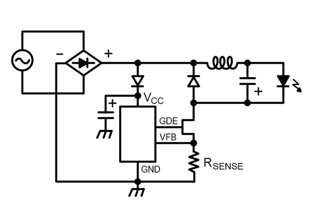
Figure 2. High transmission of silver nanowires at low resistance (Photo courtesy – ClearOhm silver nanowire material by Cambrios Technologies)

Aesthetic Lighting
OLED lighting is not a point source and, therefore, does not need to be diffused or set at a distance from the area that needs to be lit. OLEDs emit light all through their surface and can be used to create aesthetically pleasing lighting structures of various forms and sizes. Imagine an elegantly shaped lampshade emitting light instead of the shade diffusing the light from the lamp within. Lights in any form factor that needs to be bent, curved or flexed, needs flexible transparent conductors. This can be achieved easily through the use of silver nanowires rather than thick and brittle conductors.


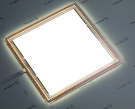
Figure 3. OLED lighting tiles. Photo courtesy – Panasonic

OLED devices can serve a dual purpose of being a window or a light. They can be made transparent – a window that you can see thru during the day and that would emit light at night. The skylights and car sunroof could not only allow ambient light to enter, also could become lamps at night. In such applications, it is important to have very transparent layers of OLED materials, another area where silver nanowire networks play a huge role.

In addition, OLED lighting can offer shades of color previously not possible with conventional lighting. Better color tuning is possible with silver nanowires, and OLED lights can offer a more precise shade of color for premium lighting applications.

2.5D Lighting
OLED lights can be produced on plastic substrates and coated with silver nanowires. These types of flexible and rugged form factors can be deployed on non-flat surfaces, such as the dashboard of a car. This type of 2D and 2.5D lighting systems are very desirable in high-end consumer devices, retail stores and museums where any surface can provide changeable color. The traditional transparent conductor materials like ITO (indium tin oxide) are brittle and don’t lend themselves to bending or shaping, hence newer materials such as silver nanowires, which are malleable and ductile, are preferred.

Thinner, Lightweight, Rugged
Silver nanowires complement OLED in that both materials are thin, lightweight and very rugged. The thin and lightweight features make them suitable for applications such as aircraft lighting and illuminating skyscrapers, and the rugged nature of the system (both OLED and silver nanowires can be coated on plastic or thin glass) makes them suitable for outdoor public venues, which typically require lighting that is not only bright but also unbreakable.

Conclusion
LED and OLED technologies will reshape the lighting market with more efficient devices that require less power and offer flexibility in design at lower overall cost. While LED technology is way ahead in replacing conventional lighting technologies, OLED lights will follow and offer lighting solutions that we have never had before. Silver nanowire technology has begun to enable these emerging applications.

Categories Blog

Enabling SSL Adoption Through Intuitive Interconnect – Part II

Last month we discussed interconnect of the Chip on Board LED device within a luminaire utilizing a TE Connectivity (TE) scalable or Zhaga compliant socket.  This month we’ll move another layer away from the light source and look at the various device-level interconnects commonly used in lighting applications. Lighting interconnects span a broad range of options from board-to-board, wire-to-board, surface mounted and inverted through board technologies.  The multitude of interconnect options for the fixture designer can be confusing, so let’s spend the time speaking about the attributes and merits of common interconnect classifications used in lighting systems.

Board-to-board applications: This connector technology allows the direct connection of two printed circuit boards. In lighting applications, this is usually in an end-to-end fashion. While a number of board to board options exist, a specific example shown is TE’s Hermaphroditic connector. This connector allows for end to end mating of board assemblies and also allows for horizontal and vertical axis mating enabling 90° and 180° articulation.  Linear, multi-segment, solid state lighting (SSL) board assemblies commonly used in cove lighting or linear lighting fixtures are ideal applications for this type of interconnect.

Wire-to-board applications: This category of interconnection can be further segmented into sub categories; two-piece separable, one-piece removable and one piece permanent. All accomplish the same fundamental task of bringing a wire to a printed circuit board in a simple, solderless approach. An example of a separable wire to board connector can be seen in TE’s low profile, micro MATE-N-LOK connector shown in the image at the right. A one piece removable solution is best illustrated by TE Connectivity’s innovative line of poke-in connectors that includes the micro poke-in wire SSL connector. Lastly, a one piece permanent connection between a wire and board can be accomplished with an insulation displacement connector such as TE’s SMT IDC connector. Termination with an IDC connector is as simple as inserting the un-stripped wire and pressing the stuffer cap down. The common thread shared by all these wire to board connectors is they are all low-profile wire to printed circuit board connectors designed specifically  for LED lighting systems whether they be channel lettering lighting strips, general illumination LED fixtures, architectural cove and valence lighting,  or LED modules for other applications.

There is another unique wire to board product that is worth noting here as well. The inverted through-board style of connector products provide an unobtrusive interconnect to printed circuit boards. By rotating the mating axis to mate from the underside of a PCB, connector exposure and wire routing issues on the LED side of the board are minimized.  The result is a clean, minimally obstructed light emitting surface ideal for use with LED array implementations in downlight, spotlight and even street-lighting applications.

To close, the interconnection is often one of the last items to be considered in a lighting design. The wrong selection can have long term ramifications in manufacturing, reliability and field repair. With a little forethought and understanding of interconnect options, design, assembly and repair can be optimized in lighting systems. Consider the following during your design efforts:

  • Is this a board to board application? If so, can this be accomplished with a direct board to board mating connector system or is a header/wire jumper assembly required by the application?
  • For wire to board applications is a separable wire to board interconnect required or can the wire be terminated with a one piece semi-permanent or permanent connector?
  • How many circuits need to be accommodated by the connector?
  • What is the end fixture application and what are the governing agency standards required by the fixture?
  • What is the voltage and current rating required?
  • What are the particular environmental constraints required (temperature, humidity, shock/vibration, ingress protection, etc.)?
  • Does your application require positive latching or is a friction latch acceptable?
Categories Blog

Which Driver Topology to Choose

Designing optimum LED drivers for Industrial, commercial and consumer applications requires a clear understanding of the application requirements. To achieve power factor correction, low total-harmonic-distortion (THD) and good output current control while meeting increasing cost and efficiency targets, only the most appropriate switching topology will suffice. Since there is no standardization in LED load voltage requirements, no single “best topology “exists. 

The aim of this month’s article is to explore off-line conversion and examine the factors that determine where buck, buck-boost, tapped-buck and flyback topologies are most effective.

Highest efficiency and lowest cost, input voltage range, output voltage range, THD, PF, regulatory requirements and the cost of isolated versus non-isolated topologies are all factors that need to be considered in selecting the appropriate driver.

Available Topologies
The simplest switching conversion approach is to use a buck converter – it has the lowest component count, a very simple (low cost) magnetic component (an inductor) and the highest efficiency.  The use of single stage combined PFC and CC controllers means that for PFC and low ATHD, buck converters are an attractive choice for non-isolated designs.


Figure 1. High-Side Buck Circuit using a Combined PFC and CC Output Integrated Control + Switching IC (Note that a high value aluminum electrolytic bulk capacitor is not required) [3]

Buck converters cannot provide functional isolation and requires the input voltage to be higher than the output voltage to work. The latter issue is important when considering THD. It can be shown that in order to meet EN61000-3-2 C/D standards for THD, the output voltage from a low-line input buck converter must be less than approximately 35 VDC. This limit is needed to keep the conduction angle (the proportion of the switching cycle over which the switching circuit is able to conduct and therefore influence input current wave-shape) high enough to effectively shape the input current to meet THD limits. For high-line applications, the maximum output voltage is approximately 70 to 75 V. In addition, Buck converters are not good at controlling voltage step-down if the ratio of input to output voltage is greater than approximately 8:1 due to duty cycle limitations in the controller.

Buck-Boost Converter
Buck-boost conversion is the next alternative – component count is similar to buck designs and efficiency is also very high. Buck-boost converters operate across a wider portion of the available conduction angle and so can provide good THD for higher output voltage designs. They have a similar problem with isolation and duty cycle limited input/output voltage ratio as buck converters.


Figure 2. Non-Isolated Buck-Boost Converter Employing Combined PFC and CC Single Stage Converter IC


Tapped-Buck Converters
The next category to consider as a possible solution is tapped-buck converters. The more complex winding structure of the magnetic element introduces a cost and efficiency penalty. However the transformer/inductor nature of the winding structure allows a turns-ratio type adjustment of output voltage and current, making tapped buck converters good for standard designs where the input to output ratio precludes the use of a buck or buck-boost topology. It is appropriate to consider the tapped buck converter as analogous to a non-isolated flyback converter


Figure 3. A low Power Tapped-Buck Converter (With no PFC stage)
Note the Wide-Input Voltage Range


Flyback Converters
The final category of LED driver we will consider is the flyback converter. The converter can be implemented as either isolated or non-isolated and the turns-ratio capability of the transformer allows for pretty much any ratio of input to output voltage. Due to imperfect coupling between primary and secondary windings, as well as primary parasitic capacitance, the more complex winding arrangement leads to increased cost and power losses. Flyback converters are overwhelmingly used for isolated LED bulb designs and use either a passive-valley fill PFC circuit (Valley fill is acceptable for 0.7 PF applications but induce 8 to 10 percent efficiency penalty in reaching the 0.9 PF required for commercial applications), or higher-efficiency combined CC and PFC converters that are available today.


Figure 4. High Efficiency Combined PFC and CC Converter in an Isolated Flyback Topology


Choosing the Right Topology
A summary of the decision process to select between different topologies is shown below. The selection strategy assumes the following order for designs: Buck →Buck Boost →Tapped Buck → Flyback. The order is weighted; highest efficiency and lowest cost being the most desirable requirements.


Figure 5. Topology Selection Flow Chart

Only if the best topology for each design is selected, can performance be guaranteed and the best design delivered. Every design will be different but all can follow the methodology described in this paper for deriving the most ideal solution for each application type.

Categories Blog

Better than L70 for Interior Spaces?

Those of us who have been pushing solid state lighting for the past six-plus years are used to preaching about its benefits of high efficiency, fine optical control and expected lifetimes greater than anything else available.  Why?  Because from A-lamps to area lights, we need to communicate an intrinsic benefit to asking for the 2X-20X premium over the incumbent technology.  Outdoor lighting specifications, which have been predominantly based on HID sources, are quite rapidly changing to solid state lighting because a solid ROI can be communicated on those three aspects. It’s a tougher case for solid state lighting in conditioned interior applications where the efficient (and inexpensive) linear fluorescent is currently king. Solid state lighting manufacturers rely on the newly-attainable efficiency gains over fluorescent luminaires as the primary value proposition.  However, a rumbling of lumen maintenance claims as high as L90 are beginning to emanate from lighting manufacturers in an effort to add value to interior solid state lighting.  Is this all smoke and mirrors, or is there legitimate value for a L90 lifetime specification?

LED lifetime for general lighting applications is traditionally defined as the L70 lumen maintenance point, at which time the light output has depreciated 30 percent from its original value.  The industry settled upon this point for defining lifetime because it represented the threshold of the human eye for detecting reductions in light output.  Was this a little overzealous?  Probably, but we needed something.  At least with L70, there would be a perception of depreciation, although over the five-plus years of operation, it would be quite difficult to detect.  Should L90 ever be adopted, we’re essentially declaring end-of-life before the eye can ever see a difference!  Pretty ironic indeed.

Admittedly, this is not new.  L90 is clearly in response to the newer 800 series T8 lamps that are claiming L90+ lumen maintenance over 40,000 hour-plus periods.  Should this be the benchmark?  Let’s keep in mind that these values are really only possible on a bench top.  A T8 lamp produces its peak lumens at a 25°C ambient and a T5HO at 35°C.  The problem is, the luminaire enclosure, surrounding optics and environmental ambient rarely, if ever, keeps the lamp even close to these temperatures!  A brand-new linear fluorescent troffer or suspended direct-indirect could, in-fact, begin its life well below L90, but this fact can be hidden in relative photometry.  Did we care (or even notice) then?

The temperature dependency of LED sources is why absolute photometry is specified by IESNA LM-79.  It certainly provides for more accurate light output from the luminaire, but it is not without its own demons that will be problematic for a legitimate L90 specification—that necessary evil known as binning.  Despite the diligent efforts of LED manufacturers to control their processes from die fabrication to packaging, all LEDs have some variation in terms of chromaticity and flux that must be tested and quantitatively grouped, or binned, into a predetermined range of values.  This range of values is usually a 10 to14 percent variation on flux.  The luminaire manufacturer then procures the LEDs to that binning specification, which will contain discrete LEDs of all values in-between.  On top of that, every LED manufacturer claims a measurement tolerance of 5 to 7.5 percent on their flux measurement.  All of this potential variation together means it’s very possible that a brand new LED luminaire will leave the factory well below L90!

Whether or not the products ship out of the factory at full output or below L90, there is a high probability that it will not be caught and relamped.  Why?  Because the only approved method for assessing LED luminous flux will be to test each product in an integrating sphere by a laboratory certified to conduct LM-79 testing.  To that extent, products will likely not even undergo a re-lamping at L70 since it’s still not to a point where users will find the lighting uncomfortable, let alone any clear indication that end-of-life has been reached.  Lumen maintenance is not a definite point in time that can be marked with a calendar—it’s a function heavily dependent on tens, if not hundreds, of variables not accounted for in any end-of-life projection.

L90 sounds really appealing on paper, whether it’s LED or fluorescent, especially within the game that is specification lighting.  When initial output and end-of-life lie so closely together and warranties are established around those qualities, that manufacturer is accepting a very high degree of risk in order to capture a bit of attention.  We can’t fault them for that, but let’s have a realistic expectation of what the technology is capable of providing and make sure there is actual value provided that offsets the risk. This isn’t uncharted territory.

Categories Lighting

The Difficulty with Daylight Hold-Off Controls

The call for improved energy efficiency and government/energy code requirements are driving a need for greater use of lighting control. One such example is the new federal requirement that all states adopt building codes that are at least as stringent as the most recent American Society of Heating, Refrigeration and Air Conditioning Engineers (ASHRAE) building code (90.1-2010) by October 2013.� That code requires automatic shutoff and dimming in many space applications, and will encourage numerous construction projects to go beyond that by connecting lighting systems to building management systems.

So, reducing electric lighting loads when daylighting exists makes sense, however, implementing this concept with the introduction of daylighting controls is not quite as simple. First, let’s take a look at the two types of daylighting systems; closed-loop and open-loop:

Open Loop: The photo sensor does not respond to, or “see”, the electric light that it controls.

Closed Loop: The photo sensor senses and responds to the electric light that it controls.


Closed loop systems are generally preferred since they adjust for any changes in the space and react and adjust to what is actually happening. For example, in a parking garage application one could have a situation where a series of daylight openings are blocked by large vehicles or a construction project where significantly less light is contributing to the space; an open-loop system would recognize the sun is out and dim the luminaires (incorrectly), whereas a closed-loop system would recognize the space is actually still very dark and would keep the fixtures at higher power to compensate for the blocked daylighting.

Open-Loop and Closed-Loop Sensors – Where Do We Put Them?
The difficulty with closed-loop daylighting controls is now we are asking the control system to understand how much of the daytime lighting contribution is from the luminaires, and how much the contribution is from the sun.

The challenges with open-loop systems are that the sensors are typically remote from the fixtures, and the system cannot account for variations in light. Many controls manufacturers have side-stepped this issue by utilizing an open-loop approach where the sensor resides in the luminaire, this is referred to as “Daylight Hold Off.”

Wattstopper, a lighting controls company, refers to this approach in their installation sheets as “Light Level Feature,”� which holds OFF and turns OFF lights when the space is occupied and adequate ambient light exists. When the light level drops below the set level it will turn the lights ON when the space is occupied. The factory setting is for maximum, meaning that even bright ambient light will not cause the sensor to hold the lights OFF if it detects occupancy in the controlled area. 

We know that open-loop systems measure the daylight contribution and alter the luminaire light output based on the readings from the photo sensor. Normally, an open-loop system has a sensor mounted so it’s in direct view of the daylight (see figure above), in other words remote from the luminaire. But in this case the photo sensor is in the fixture, how would that work?

Short Answer: Not very well.

Long Answer: An open-loop system must only read the daylight contribution in the space, so in order to accomplish this task while the sensor resides in the luminaire the sensor must wait until the luminaire is shut-off before the device can take measurements. At that point, when the luminaires are off, the sensor will take a reading and determine if the daylight contribution exceeds the user selected light level on the control — if the light level is, in fact, exceeded. Once the space is re-occupied, the system will hold the lights off, or in a lower level state.

If there is enough activity so the lights don’t shut-off, then this type of open-loop daylight control is rendered completely ineffective. An ideal application for hold-off controls would be in a small office. Conversely, in a space that has a lot of foot or vehicular traffic, this would be a poor application because it is conceivable, and in many cases likely, that the luminaires would not dim at all during the entire day.

The difficulty with closed-loop controls is the commissioning of the luminaires and the controls. Many closed-loop controls systems require that the controls are initially turned-on during the night so that the levels being read are only electric. While this is effective, it is sometimes very difficult to manage and can be costly because highly-paid technicians would need to attend the location after-hours.

Conclusion
The ideal solution is to have controls that work on the closed-loop principal – always measuring both electric and daylight levels simultaneously. Utilizing controls that can be commissioned for light level without technicians present after-hours provides the best scenario of easy and cost effective commissioning with accurate daylight harvesting control.