Categories LED

LED Warranty Protection – Buyers Beware of the Fine Print

What is in a warranty? Most buyers of commercial products expect that the manufacturers will stand by their technology and replace it if there is failure.  For LED lighting, the LED warranties are not a promise to save money through energy reduction. LED warranties are a promise that the lights will perform at levels that buyers expect. The key warranty questions in the growing LED marketplace are what defines LED fixture failure, what triggers a replacement, and how long is the coverage.  Buyers should proactively ask these questions to the manufacturers or the suppliers and ask to review the actual warranty language as part of the assessment process in choosing LED fixtures.

The majority of commercial LED light manufacturers around the world offer 5 Year LED Warranties to meet the minimum requirements of the DesignLights Consortium (DLC) for its Qualified Products List (QPL). The minimum protection along with other criteria serves as the guide for most utility companies to approve rebate eligibility. One of the problems with the DLC warranty criteria is that it only requires the 5 years and does not get into the details of what is covered. This creates a potential false sense of security for buyers. With tens of thousands of applications and listed LED products, DLC does not have the resources to review the qualitative details of the LED warranties. So, buyers need to take the initiative to assess the value of the protection themselves.

The few manufacturers that offer a 10 year LED warranty often have “fine print” with limitations on daily hours of operations, carve-outs outs for lesser protection on the LED drivers, or restrictions on warranty transfer if the original owner sells the building or business. Buyers beware, because many LED warranties also define “failure” with surprisingly high percentages of diodes, and they do not include protections against color shift or total output degradation relative to L70 standards.

Beneficiaries of a Strong LED Warranty:

PROPERTY OWNERS: A 10 Year LED Warranty benefits owners and managers of facilities that have areas with 24 x 7 illumination such as office building emergency stairs, hospitals, hotels, parking garages, fire and rescue centers, dormitories, and any emergency egress lighting for facilities such as schools.

SERVICE and FINANCING PROVIDERS: A 10 Year LED Warranty benefits Energy Service Provider Companies (ESCOs), commercial lighting solutions providers, and companies providing Saving Share or Lighting as a Service (LaaS) programs.

For performance contracts, the service providers are often obligated to keep the lights on. So, a longer warranty and more reliable products help reduce their maintenance and replacement costs. Plus, as financing plans for energy saving lighting become increasingly popular, many lenders are requiring warranties that do not have the “fine print,” giving the manufacturers a way out of replacing failed technology. Naturally, lenders also desire LED warranty coverage to match their financing terms. So, if the terms are extended to roll-in solar or HVAC on a facility, a strong and long LED warranty for the lights is favorable. 

Watch out for the Drivers:

Over the past two years, some LED companies were confident enough in the longevity of their diodes that they started offering 10 year LED warranty coverage on their LED fixtures, given in-field and laboratory testing. However, the warranties sometimes included limits of up to 60,000 hours on the external driver (6.84 years at 24 x 7 operations of 8,760 hours per year).  The drivers were the “Achilles heel” of the systems. Recently, some LED manufacturers have started offering 10 Year LED warranty protection on complete diode and driver systems, in part because external drivers with “potting” help insulate against damaging heat gain.

Categories LED

LED High Bay Luminaires – Ready for Prime Time

High bay lighting is the most common type of lighting used in commercial facilities that have high ceilings and require high foot-candle levels. They are ideally suited for warehouses, cold storage, airport concourses, grocery stores, gymnasiums, convention centers and other large indoor spaces with mounting heights between 15 and 40 feet, and ambient temperatures between -4°F and 131°F.  While high bay lights have traditionally used high intensity discharge (HID), metal halide (MH) or florescent lamps, many specifiers and facility managers are changing to LED luminaires. 

Properly designed and engineered LED-based high bay luminaires can offer big advantages for commercial applications. However, it’s important to consider LED luminaires that take a systems-level approach that includes driver design and thermal management, rather than just retrofitting LED “bulbs” into existing fixtures.  Thermal management is critically important to achieve the reliability expected from LED luminaires.  Extreme temperatures, both hot and cold, are common in high bay environments and can have a negative impact on the performance of electrical components.

Compelling LED Lamp Life 

  • 50,000 hours or better (5 years or more)
  • Minimizes the cumbersome maintenance of high ceiling applications

Advantages of LED Technology

  • Exceeding government mandated efficiency standards
  • Controlled distribution of light for enhanced uniformity
  • Higher luminaire efficacy

Let’s examine in more detail the many advantages of LED technology for high bay fixtures and a few application examples.

Warehouse Lighting
According to the Department of Energy, lighting uses as much as 29 percent of the electricity generated in the US and for industrial facilities, traditional lighting:

  • Uses 38 percent of the energy in a typical warehouse
  • Requires 15 percent of the energy in a refrigerated warehouse
  • Consumes 75 percent of a warehouse facility’s energy expenditures when maintenance is factored in with energy costs

Here’s where LED luminaires’ dramatic energy efficiency really makes an impact, particularly because many facilities that illuminate with high bays are in operation 18 to 24 hours a day. Typically, lighting is viewed as a fixed expense, but it shouldn’t be; energy costs can be dramatically reduced, up to 75 percent, and maintenance can be virtually eliminated through the installation of LED luminaires. Additionally, paired with occupancy sensors and/or dimmable components they provide even greater energy efficiency.

Further power savings are achieved from turning off the fixtures when not in use. Workers often leave the traditional lights on continuously because they take so long to warm up to full brightness. LED luminaires light immediately, eliminating the need to have them on all the time.

Many LED retrofit installations don’t require a one-to-one replacement so the combination of using fewer fixtures for shorter periods of time provides a lower energy bill and significantly reduced maintenance expense.

Cold Storage Lighting
With large, open spaces to cool, as well as sizable lighting requirements, cold storage facilities can consume vast amounts of energy.  As in any business, owners and managers of cold storage warehouses are often faced with minimizing their operating costs.  The energy used by the refrigeration system is often a major contributor to this cost of operation.

Conventional lighting and refrigeration systems typically work against each other.  Lighting systems generate heat, which the refrigeration system needs to remove.  In addition, lower temperatures typically reduce the efficacy of lighting systems.  Therefore, more power is required to generate the desired illumination, which in turn, increases the load on the refrigeration system.

Facilities can save tens of thousands of dollars in yearly electric costs, and cut harmful emissions by thousands of tons by implementing a handful of simple, cost-effective efficiency measures to reduce electrical consumption and have a payback period of three years or less such as installing LED luminaires. [1]

Only certain technologies, such as LED luminaires, are capable of functioning for cold storage needs at temperatures that range from zero degrees to -40°C.

Gymnasium Lighting
For years, the standard method of lighting gymnasiums has been the 400 W MH high bay.  This has led to gyms with deteriorating light levels and poor playing conditions that are expensive to operate. The MH system is essentially an “on-off” system that provides little control over light levels.  Also, these lights require 10 minutes or more before they reach their full light level.  After they are turned off, they require a similar amount of time before they can be turned back on again.  As a result, these lights are typically turned on in the morning and kept on until the building closes, regardless of whether there are any activities in the gym.  Additionally, MH use a lot of energy but produce less light as they age, giving gyms and other facilities poor illumination.

LED high bay luminaires deliver instant white light with no restrike or run-up delay.

LED Lamp Life
Correctly designed LED will not fail catastrophically, but rather slowly dim. LED luminaires are determined to have “failed” when light output reaches 70 percent of original output. In fact, well designed fixtures can last over 50,000 hours making non-scheduled equipment downtime due to lamp failure nonexistent.

How long is 50,000 hours?
Based on the length a fixture is illuminated per day, here is what a 50,000 lifetime translates into on an annual basis:

Hours of Operation –  50,000 hours is:
24 hours a day 5.7 years
18 hours per day 7.6 years
12 hours per day 11.4 years
8 hours per day           17.1 years

With LED luminaires, maintenance costs are minimized as relamping may not be required during usable lifetime of the product. Another important consideration given that high bays are ceiling-mounted and may need the use of a lift to change out the burned fixture.

LED Illumination – Ready for Prime Time
Debate continues about whether LEDs have the output in lumens. Through advancements in technology and manufacturing, bright white LED luminaires for commercial lighting applications are in the market. Recent legislation in the US has led to the phase-out of mercury vapor ballasts and lamps as well as 150 to 500 watt MH luminaires. LED technology fills these needs, while far exceeding government mandated efficiency standards.

A LED luminaire incorporates an array of point sources that direct light precisely where it’s needed, with very little scattering or loss. Light distribution is controlled by the placement of LEDs, as well as by efficient use of optics that take advantage of the focal point presented by each individual LED.

Since traditional lamps are high-intensity near-point sources, the optical design for these luminaires causes the area directly below the luminaire to have a much higher illuminance than areas farther away from the luminaire. In contrast, the smaller, multiple point-source and directional characteristics of LEDs can allow better control of the distribution, with a resulting visible improvement in uniformity.

LED luminaires use different optics than traditional lamps because each LED is, in effect, an individual point source. Effective luminaire design exploiting the directional nature of LED light emission can translate to lower optical losses, and higher luminaire efficacy.

Categories LED

New PCB Materials for Thermal Management of High Brightness LEDs

Despite the enormous efficiency advantages of LEDs, when compared to incandescent lights, they still waste around 70 percent of the electrical energy put into them. This energy appears as heat and needs to be conducted away from the LED to maintain a safe operating temperature. Overheating an LED severely limits its lifespan and impacts on efficiency and color quality.

Existing thermal management technologies are limiting the speed at which LEDs can penetrate into certain high-powered application areas. They simply cannot deliver the technical performance required at acceptable cost.  Huge opportunities therefore exist for companies that can find a more cost-effective substrate solutions for high brightness LEDs.

Conventional Approaches
The key characteristics required for a thermal substrate are excellent thermal conductivity and good electrical isolation. This limits the materials choice. Aluminum nitride (AIN) has traditionally been used in high brightness chip on board (COB) LEDs and as a submount for high power LEDs.

Whilst aluminum nitride is thermally more than up to the job the exotic manufacturing process – requiring carbonthermal reduction of aluminum oxide or direct nitridation of aluminum, together with the extremely high temperatures involved – makes it very expensive. Currently available machinery limits the size that can be manufactured to around 4 inches by 4 inches. It is also quite brittle, which in turn limits the yield. Add to this the requirement for specialist processors and you end up with a very uneconomical product.

The use of aluminum itself is a very compelling option – it’s a great thermal conductor, cheap, readily available and extremely robust. What it lacks is electrical isolation. The standard approach of adding an epoxy to the surface to produce a dielectric layer reduces the thermal conductivity too much for use with high brightness LEDs so an alternative is needed.

Attempts to anodize the surface of aluminum to combine the thermal conductivity of aluminum with the dielectric properties of a ceramic have failed repeatedly over the years – the anodizing process leaves gaps in the dielectric layer, which can create electrical short circuits.

A New Approach:
Cambridge Nanotherm has taken a new approach, patenting an entirely original electrochemical process for creating a dielectric on the surface of aluminum. This process produces a composite substrate with thermal properties comparable to AlN but far more cost effective.

Nanotherm’s approach converts the surface of a sheet of aluminum into a dielectric nanoceramic layer. The crystals formed can be as small as 30 to 60 nanometers. Because the nanoceramic is formed by a conversion process, this ensures a perfect and robust bond between the dielectric and the aluminum resulting in a uniform layer of ceramic, which is a perfect dielectric.

The nanoceramic dielectric layer can be as thin as 3 microns, this makes the thermal path between the LED chip and the aluminum as small as is feasibly possible, resulting in extremely high overall thermal conductivity.

What’s more the nanoceramic layer can be grown just as easily on complex 3D shapes. This is key to the creation of vias. With AIN, creating vias is expensive, complex and creates mechanical weakness. With the Nanotherm process, holes can simply be drilled in the aluminum before processing and the ceramic dielectric will be deposited uniformly on the surface of these through-holes.

The Result:
The resulting nanoceramic dielectric layer has a thermal conductivity of around 7.2 W/mK and a dielectric measure of about 50 V/um. For COB LEDs, the finished product has a thermal conductivity of 152 W/mK (measured between the top surface of the copper that carries the wiring trace and a 0.6 mm aluminum sheet). This outperforms many low-grade and mid-grade AIN products.  Double-sided metallization, with through-holes yields sub-mounts for LEDs.

Cost is always a factor. With an industry in desperate need of finding ways to bring the cost of LED products down to a point that the mass market are comfortable with, any saving is good. Not only do nanoceramic substrates offer a significant cost advantage over AIN, they can also be processed through standard PCB manufacturing facilities, bringing the scale and cost advantages of the traditional PCB industry to bear on the LED packaging market for the first time.

Nanoceramics open up an entirely new class of thermal management aimed squarely at the high power LED market.

Categories LED

Narrowing the Field of LED Luminaires


You know it’s a hot topic when the Wall Street Journal is writing about it. A few weeks ago, the WSJ wrote about a LED manufacturer’s product qualifying for utility rebates through the DesignLights Consortium (DLC). So what makes this so newsworthy? With the prices of LED luminaires already decreasing over the years, the opportunity for end-users to receive utility rebates for upgrading to energy efficient LEDs really helps shorten the ROI and drive more adoption of this technology. Essentially, utility rebates are lowering the upfront cost of new energy efficient lighting.

What is the DLC?
For those of you not aware, the DLC is collaborative effort between utility companies and regional energy efficiency organizations, to help buyers implement improved design practices in all areas of the commercial lighting market. According to their website, “the DLC promotes quality, performance and energy efficient commercial sector lighting solutions through collaboration among its federal, regional, state, utility and energy efficiency program members; luminaire manufacturers; lighting designers and other industry stakeholders throughout the US and Canada.”

Throughout its 17-year history, the DLC program has driven the lighting market towards innovation by providing information, education, tools and technical expertise for cutting-edge technologies. Since 2010, the DLC has administered the Qualified Products List (QPL), a leading resource that distinguishes quality, high efficiency LED products for the commercial sector. Today, the QPL sets the bar for efficiency program incentives across the US and into Canada while informing manufacturer product development.

Utility Rebate Programs
Utilities offer two types of rebate programs: prescriptive and custom. Prescriptive rebates provide a set amount for each fixture replaced. The dollar value of custom rebates is based on the total energy savings of a specific project.

In a report by Groom Energy and GTM Research, Enterprise LED 2012: Commercial and Industrial Market Trends, Opportunities and Leading Companies, utilities across the country show limited prescriptive rebate support for LED lighting. However, as the LED market matures, utilities will aggressively start moving. Additionally, this report states, “When satisfied that savings can be successfully achieved, utility program managers will typically authorize custom rebate amounts of up to 50 percent of the entire cost of the project, as opposed to a prescriptive rebate for each fixture.” And some of this is already occurring at a rapid pace. For example, New York is second only to California in dollars spent by utilities in energy efficiency rebate incentive programs. According to an article in Green Tech Efficiency, in 2008, there was approximately $3.1 billion available in total US rebate dollars, with the money concentrated in 10 states. The figures are expected to more than double in the coming years, with $7.4 billion to $12.4 billion available by 2020.

California, New York, Florida and Massachusetts have some of the most robust energy efficiency programs, but others, according to the Consortium for Energy Efficiency, like Pennsylvania, Illinois, Arizona and Ohio, have started building new programs entirely, North Carolina and Michigan are also increasing spending, according to the Lawrence Berkeley National Laboratory.

MORE on LED REBATES
The most accurate resource for energy rebates and incentives is the Database of State Incentives for Renewables and Efficiency, which is available online here. It details a comprehensive list of rebates and programs by federal, state and utility companies to help buyers determine whether projects qualify for rebates and incentives. It’s also a dependable resource for energy professionals and lighting distributors to use as a cross check against the DLC lighting lists.

Do Your Homework
Typically, when retrofitting with LEDs or choosing to install LED luminaires in new construction, the facility manager or building owner will hang a number of lights from different manufacturers for comparison. While this is an important part of the lighting selection process, reviewing the DLC’s Qualified Products List and the Database of State Incentives for Renewables and Efficiency streamlines fixture choices and aids in making the best decision.

Categories LED

LED Match Making – The Value of Photometric Analysis

Many commercial building owners and operators may have more light than they need in certain areas and less light than they need in other areas. When considering an LED retrofit, do not just buy new lights for the energy savings, but take the time to get the right type of lights to meet your business operating needs. Photometrics Analysis is a great way to “see” a plan and elevations of the current foot candle light levels and the potential to increase or decrease levels where needed.

As an example, for a national auto service chain, Monro Muffler and Breaks, one of the managers at a Connecticut location spoke about the need for more light in the service bays to show customers what needed to be fixed on their cars. The managers also spoke about a brighter more appealing overall look to their service centers to attract more customers. For a top BMW dealership in Virginia, the requests included improved light quality to showcase the vehicles. They wanted customers to be able to see the vehicles with brighter light and with color temperatures to more closely match how the vehicles appear outside in daylight. Since color temperature is measured in Kelvin and Kelvin impacts output in lumens, the lumens impact the foot candles. A photometric analysis helps shape the optimal lighting solution. In another example, an Anheuser Bush beer distributor, in Pennsylvania, with over 300,000 sq. ft. wanted to ensure 30 foot candles at the floor as well as on the storage racks. They wanted to be able to load the trucks more quickly with fork lift truck operators clearly seeing the palette labels under brighter light. In this case, the photometric analysis included both floor plans and elevations. The results of the study drove the inclusion of reflector systems where appropriate on the LED high Bay light fixtures. In each of these examples the right amount of light played a role in improving the operations of the business not just a reduced energy bill.

To better understand photometric analysis, here are some highlights from Wiki.

Photometry is the science of the measurement of light, in terms of its perceived brightness to the human eye.It is distinct from radiometry, which is the science of measurement of radiant energy (including light) in terms of absolute power. In modern photometry, the radiant power at each wavelength is weighted by a luminosity function that models human brightness sensitivity. Typically, this weighting function is the photopic sensitivity function, although the scotopic function or other functions may also be applied in the same way.

The human eye is not equally sensitive to all wavelengths of visible light. Photometry attempts to account for this by weighing the measured power at each wavelength with a factor that represents how sensitive the eye is at that wavelength. The standardized model of the eye’s response to light as a function of wavelength is given by the luminosity function. The eye has different responses as a function of wavelength when it is adapted to light conditions (photopic vision) and dark conditions (scotopic vision). Photometry is typically based on the eye’s photopic response, and so photometric measurements may not accurately indicate the perceived brightness of sources in dim lighting conditions where colors are not discernible, such as under just moonlight or starlight. Photopic vision is characteristic of the eye’s response at luminance levels over three candela per square metre. Scotopic vision occurs below 2 × 10−5 cd/m2. Mesopic vision occurs between these limits and is not well characterized for spectral response.

Based on this description above, the net of the photometry science is that it is more complicated than most business owners or operators care to learn. So, the tip below is as simple as working with the right people to navigate the complexity.

Top Tip on LED Light Matching with Photometrics:
Choose a commercial LED lighting manufacturer or solutions provider that has the software to run photometric analysis on your facility before making a major LED purchase. This gives you the power to review your options with objective data laid out in easy to review, multi-color floor plans and elevations.

Categories LED

Tipping Points, Toothaches and LEDs (?)

Scene 1: A toothache had me sitting in a comfortable endodontist’s chair, surrounded by state-of-the-art dental equipment. The smell of paint and new carpeting, in addition to soothing music, was in the air, and the lighting quality was both very good and comfortable. To avoid thinking about a possible root canal, I distracted myself by listing what I thought was lighting the space without looking up. I started noting my observations in my head. CCT was warm (probably 3,000 K), very good CRI (probably 90+), high R9 (good skin tones, certainly positive, maybe by a lot), high scalloped shadows on the wall (several “smaller” fixtures?), well-blended lighting on the walls a couple of feet below the ceiling line (not CFLs, probably linear sources), very uniform light at work surface heights throughout the entire space, no intense glare sources showed in the highly reflective equipment surfaces (definitely not CFL). I could hear someone coming so I quickly wrapped up my lighting audit. I guessed the room was lit with 3,000 K T5 fluorescent lamps in quite a few good volumetric lighting fixtures, possibly 4-foot but probably shorter, and probably not HO.

Scene 2: After explaining the need for an immediate root canal and readying the appropriate tools and supplies, the soft-spoken endodontist said, and with way too much enthusiasm, “We have reached the tipping point!” as I was reclined into position. From my new vantage point, to my surprise, I could clearly see 2 by 2, two-lamp, U-lamp, T12 fluorescent lamps and fixtures. I didn’t see that coming.

Scene 3: Prognosticators have recently said that the “LED tipping point” is behind us; therefore, why isn’t this newly-equipped, recently-renovated, state-of-the-art office lit with LEDs? Many likely think the explanation is complex, but I think it is pretty simple. Prognosticators come and go, but “lighting” evolves.

Scene 4: “Lighting technology” is mostly important to “technologists,” whereas, a reliable, cost-effective and comfortably-lit space is what is important to the customer. LEDs are a light source technology and not a lighting product or solution. LEDs can and will enable reliable, cost-effective and comfortably-lit spaces, but that won’t happen overnight. Have we forgotten the trials, tribulations and time it took to “evolve” from T12 to T8, from magnetic to electronic ballasts, or from T8 to T5?

Conclusion: Comparing that which comprised the fluorescent “evolution” of the past 30 years to the “evolution” awaiting us in/with solid state lighting is simultaneously exciting and sobering to those who understand the potential benefits, business opportunities, added functionality and challenges which might come along with solid state lighting.  I look forward to the day when my house recognizes my approach and turns on my porch light to minimize my key fumbling, when sensors recognize me beginning to sit in my favorite chair and turn on my reading lamp to a high intensity/warm color, and when those same sensors recognize me dozing and dim that reading lamp to a much lower intensity. I am excited about a future where concepts like this surround us in the workplace. Although I wouldn’t classify most consumers and users as “technologists,” it is clear to me that most can be aggressive consumers of “technology” with smart phones, tablet computing devices and cars that parallel-park themselves being only a few examples. The work will be challenging, but interesting. The benefits will initially be difficult to document with numbers, but nonetheless evident. Patience (by all) will be required but exciting times and opportunities lie ahead for lighting that leads.

Categories LED

Driving an LED Load

In this month’s article, we address factors that influence how an LED is driven, including different driver techniques and why they are preferred for a variety of lighting applications. We look at the effects of different loads, as well as control options to drive LED loads effectively.

Constant Current or Constant Voltage?
LEDs typically require a constant current rather than a constant voltage to operate. The LEDs themselves present a constant voltage drop across the line (although the actual value of the voltage drop varies between approximately 3.2 V and 3.0 V depending on LED type and temperature).

Constant current drivers (CC) deliver a constant current to the load across a range of LED voltage conditions. For bulbs, the driver is typically designed to deliver constant current across a narrow LED voltage range (perhaps nominal voltage +/- 10 percent). These drivers are very effective in tightly specified designs (such as LED bulbs), making them application specific. However, this approach requires the design of a dedicated CC power supply.

Another approach is to use a driver that can deliver a constant voltage (CV) across a wide current range. Many CV drivers are fully isolated, simplifying the design process and removing much of the burden of meeting safety approvals, it also facilitates scalability  by adding more parallel LED strings.

In order to maintain a constant current through the LED string with a CV output (such is often delivered from ballast-type drivers), a series resistor is added, the value for which is determined by the equation:

where VDC is the nominal output voltage from the power supply, VLED is the voltage drop across the whole LED string and ILED is the desired LED forward current.

This is a very simple relationship, but the effect of circuit tolerances becomes significant. Output voltage ripple and the voltage tolerance of the driver result in dramatically increased effects in LED circuits compared to similar low-voltage drivers used for more conventional power applications.  For example, although a voltage variation of  +/- 5 percent is not large when considering the output voltage, in an LED driver with a load resistor, ILED varies according to the amount of change in the difference between driver voltage and the LED voltage – the effect on output current is magnified.

In order to achieve an acceptable design, the engineer must trade off power dissipation in the resistor against output current variation.

The human eye is relatively insensitive to light intensity and adjacent drivers subject to similar input voltage and ambient conditions tend to track each other (the difference between drivers in the same conditions will be less than the worst case described above). Therefore, in fixed or consistent conditions the effect of the tolerance in a CV LED driver may not be a major concern, provided that output voltage can be controlled within a relatively narrow range.

Primary and Secondary Control – Performance vs. Cost
To drive an LED load effectively with a CV driver, output regulation must be well controlled. Secondary side controllers that directly measure output voltage and deliver correcting information to the primary side switching stage will tightly control the output but will also add cost and shorten product lifetime (the opto-isolator, which is used to transfer information from secondary to primary, degrades over time).

In contrast, primary-side controllers do not directly monitor the output stage. Instead, they infer output performance using indirect means. A challenge with this approach is that component variation can affect output regulation. Leakage inductance in the isolation transformer can easily vary by ±15 percent in production, which will significantly degrade the output tolerance of a design.  In order to improve accuracy, primary side-controllers (such as LYTSwitch-2 LED driver ICs) use correction algorithms to compensate for inductance variation as well as line and load effects. Thus, they can achieve output regulation of better than 5 percent across line and load.


Figure 1. Load and line regulation in voltage mode for LYTSwitch-2 LED driver ICs.

The accuracy of primary side controllers with good line/load regulation coupled with the lower system cost and higher reliability of this approach results in wide utilizationfor low power drivers.

Combined CV/CC Drivers
By combining different control modes, it is possible for an LED driver to have both constant current across a variable voltage and constant voltage across a variable current.  The benefit of this technology is that the same control IC and power supply circuitry can be used for a wide range of applications and load conditions. The CC mode allows the output to deliver constant current across a wide output voltage swing (typically 2:1 or better) as well as a wide output voltage range.


Figure 2. Combining different control modes – LYTSwitch-2 LED driver IC with constant current across a variable voltage and constant voltage across a variable current.

Using On-Off control for CV operation and Variable Frequency Control for CC portions of the regulation curve results in a product that can support both CC direct LED driver and CV applications.

This approach is particularly useful for power supply manufacturers who wish to support a wide range of customer applications with a limited range of power supplies.

As we have discussed, an LED requires constant current, and can be driven using different power supply types. So far we have considered the LED load to be a string of ideal diodes which all behave the same. In the next article we will consider the effects of variations in LED characteristics and how they affect efficacy, output ripple and other circuit performance metrics; this will clearly demonstrate that it is not possible to determine circuit performance without a clear understanding of the nature of the LEDs which will be used.

Categories LED

Diving into Benefits with LED Luminaires in Natatorium

Pool Lighting – Indoor pools are hard on light fixtures. The exposure to a warm and humid environment is particularly challenging. Additionally, because natatorium fixtures are difficult to access, maintenance must be kept to a minimum.  If any fixture’s or lamp’s glass were to fall into the pool during maintenance, the entire pool needs to be drained – an expensive and time-consuming effort.

Life safety and accident prevention are the driving forces behind natatorium lighting. Because water is a reflector, reducing the glare from the fixtures is critical.  Adequate light levels, bright illumination, and consistent uniformity are also very important.

Fixtures for this application need to be at least damp location rated, offering the highest safeguard against moisture and water treatment chemical vapors. 

One way to address all of these issues is through the installation of LED luminaires.


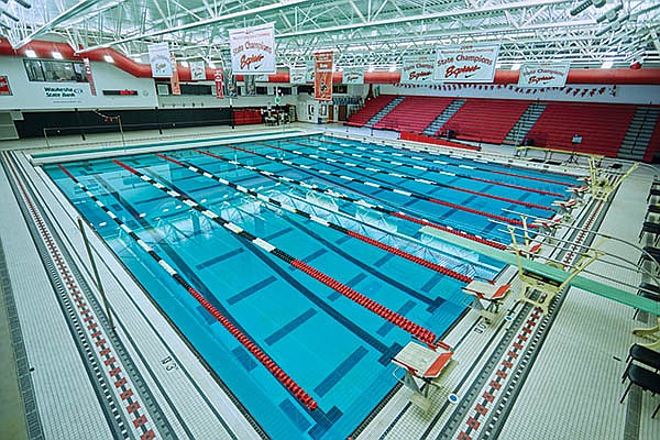
Waukesha South High School Natatorium | Waukesha, WI
South High School is Waukesha’s oldest high school, opening in 1957. Today, the 1,460 students use a swimming pool complex that was rebuilt in 2005, replacing a smaller and much older pool, spectator and locker room facility. The current natatorium is larger than in most schools, measuring 25 yards x 30 meters and the oversized perimeter accommodates nearly 2,000 spectators.

The 27,000 square-foot natatorium is used extensively by the high school physical education department, the school’s swim team and the Waukesha Express Swim Team.

Lighting – The complex was originally designed with a metal halide (MH) indirect lighting system to reflect light from the ceiling to minimize glare on the water’s surface. Over the years the ceiling and walls darkened due to deteriorating light levels and fixtures burning out, creating a cave- and dungeon-like atmosphere. Replacing the burned out fixtures was so challenging, they were typically left until there were enough to warrant bringing out the lift.

Tom Cherone, master electrician Waukesha School District, knew the lighting system needed improving:

  • spectators were complaining they couldn’t see the swimmers because the lights were so dim;
  • the low light levels were a safety issue for the lifeguards;
  • he was worried while conducting maintenance on the MH fixtures that if glass dropped and broke in the pool the 480,000 gallons of water would need to be drained;
  • and MH technology requires 10-15 minutes of “cool down to relight,” meaning that the bulbs needed to cool down enough before they could be re-lit again, which was very inconvenient.

Through Wisconsin-based Hein Electric Supply, which has a long-time relationship with Waukesha School District, Cherone learned about retrofitting the existing lighting system with LED high bay luminaires to improve illumination quality, safety and security while also reducing energy costs and consumption.
Recently, in a one-for-one replacement, 42, 1000-watt MH fixtures were replaced with 240-watt LED high bay luminaires and eight, 36-watt florescent tubes were retrofit with 80-watt LED high bay luminaires.

“The new lights are terrific,” said Cherone.  “They strike instantly, provide more lumens than our old MH lights, will last for years and are cost effective.”  “When all the fixtures are on we’re saving an astounding 70 percent in energy over the previous MH lights,” Cherone continued.

Because they emit far less heat than MH fixtures, the school will be able to run the air conditioning less in the summer months, further reducing the energy bill.

Additional power savings are achieved from turning off the fixtures when not in use. The previous lights were left on continuously because they took so long to warm up to full brightness.  These LED luminaires light immediately, eliminating the need to have them on all the time.

“At swim meets I used to apologize to the visiting teams because it was so dark,” said Blaine Carlson, CEO/head coach Waukesha Express Swim Team. “Now, with these new lights, I think we can even attract additional meets to this facility,” Carlson continued.

Cherone is so pleased with the reduction in maintenance, energy savings and consumption, and the dramatic improvement in light quality that he’s planning to replace all of the MH lights in the district schools’ pools with LED high bay luminaires.

In addition to upgrading the natatorium lighting, the district is implementing an exterior lighting program for the schools’ parking lots; saving the district more money and, most importantly, improving security through better  light levels.

Categories LED

Dinosaurs Luck Out with LEDs

In the days of old when Knights on horseback hunted dinosaurs by flashlight, electrical safety regulations were a much simpler affair. Incandescent light bulbs were installed in metal luminaires with a bit of Bakelite here and there for insulation. To make everything safe the electricity supply incorporated a fuse while an earth wire kept the metalwork at ground potential.

Then along came plastics, double insulation, residual current circuit breakers, fluorescent tubes, dimmers, and now switch mode power supplies and LEDs. To accommodate all these changes the regulations were expanded and improved.

Unfortunately, modern technology moves faster than regulation can keep up, and in the case of LED lights there is confusion as to what is appropriate and applicable.

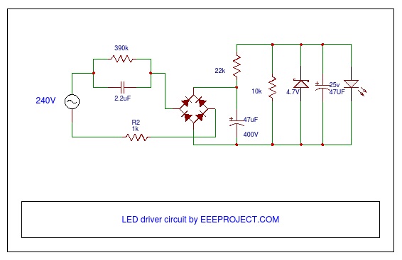
From an electrical perspective LEDs are incredibly safe: They operate at only three volts DC, so you need a resistor to actually decrease the voltage before you can use an LED in a three cell flashlight. It also means that to operate most types of LED from the utility supply requires a power supply. These range enormously in sophistication. At one extreme it can comprise a bridge rectifier and with a capacitor used as a reactive dropper. These are common in the types of cheap LEDs bulbs you might commonly find online, where the phrase “caveat emptor” seems highly appropriate. What should be present is a properly designed switch mode constant current power supply with over voltage, over temperature, spike suppression, short detection and other protective circuits.

In an application like domestic lighting, white LEDs need to be in the 5 to 10 W power range to compete with incandescent bulbs on a Lumens basis. Because LEDs are relatively inefficient, albeit miles better than incandescent bulbs, they have to be soldered on special metal-in-board PCBs to dissipate the heat produced. The PCB connects to a heat sink, which will often be accessible as the fins need to be in fresh air to provide cooling. The question then arises: How much dielectric isolation does there need to be across the metal-in-board PCB between the finger-accessible metal side and the electrical tracks connecting the LEDs to the power supply?

There are roughly 50 standards potentially applicable to LED lighting and many are still in development. Not only is there potential uncertainty over which standards are applicable, but standards are also complex documents that are written in carefully constructed English. There is good reason for this – they are intended to cover all conceivable scenarios within a precisely defined scope. Yet to an LED engineer (having a casual flick through in search of design guidance) they sometimes might as well be written in Latin.

I asked a few people in the industry how much dielectric isolation they thought was required for metal-in board PCBs used in LEDs. Unsurprisingly, the answers ranged from “50V” through “it depends” to “over 5kV”.

Making the correct choice matters because both the breakdown voltage and the thermal resistance between the LED and the heat sink are proportional to the thickness of the dielectric in the metal-in-board PCB. Keeping LEDs cool is important for sustaining their hue, brightness and longevity and also to maximise efficiency. Using a Nanoceramic for the dielectric means this layer can be extremely thin to provide good cooling yet with sufficient dielectric potential to ensure the product will be electrically safe.

Because electrical safety is of huge importance interpretation of the standards, and from there the dielectric potential of the metal-in-board PCBs, should always be left to those that are experts in the field.


Categories LED

Why Are LED Binning Ranges Important for LED Manufacturers and Their Customers?

Binning, in relation to LEDs is a practice designed to maximize effective utilization in the production of LEDs. In LED production, a single round wafer is coated with materials to create a semiconductor which forms the ‘heart’ of the blue LED. This is then sliced into small rectangles, wire bonds are inserted and the phosphor is added as a coating within the enclosure. The whole thing is then encapsulated to create a finished white light LED. That coating process creates significant inherent variations that impact color temperature, lumens and voltage of the LED. The process is not capable of producing highly consistent and strictly controlled production of LEDs.

To combat this issue, manufacturers sort production into voltage, color and lumen bins. Light output and color temperature are the most critical bin criteria that impact product performance. To sort for light output, LEDs are individually measured and sorted by lumen output into prescribed ranges. LED suppliers create their own standard set of lumen bins and provide clear information on expected lumen performance for each of their ranges. The larger a bin size – the more variation you can expect around color temperatures and outputs – small bins have tighter control.

Manufacturers select only those LEDs that meet their acceptable performances ranges – Sedna LED have four performance ranges, which is higher than the average, many manufacturers have only two. Customers buying from manufacturers with more ranges can expect less variation in their products.

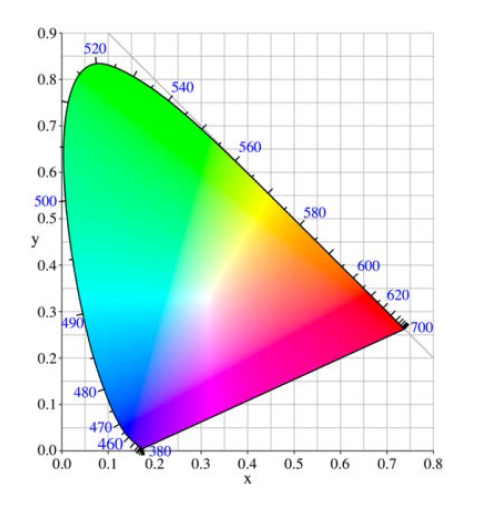
SDCM is an acronym which stands for Standard Deviation Color Matching- sometimes known as a “MacAdam ellipse”. A 1-step MacAdam ellipse defines a zone in the CIE 1931 2 deg (xy) color space within which the human eye cannot discern color difference. Most LEDs are binned at the four to seven step level, so you can often see color differences. The variable nature of the color produced by white light LEDs means a convenient metric for expressing the extent of color difference within a batch is the number of SDCM ellipses in the color space that the LEDs fall into. If the chromaticity coordinates of a set of LEDs all fall within 1 SDCM most people would fail to see any difference in the color. If the differences extend to a zone twice as big (2 SDCM) you will start to see a color difference. A 2-step MacAdam ellipse is better than a 3-set, and so on. The diagram illustrates a CIE color space diagram, where SDCM ellipses are shown at 10 times magnification.