Categories Lighting

Smarter LED Street Lighting Applications

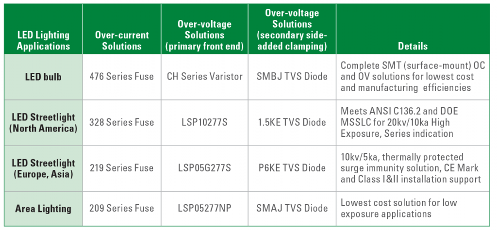
LED Street Lighting is a technology and infrastructure with evolving demands. It is not only about bringing light to an area anymore, it is about anticipating tomorrow’s needs for value added services. Until recently, designers have mostly only been able to select ANSI/NEMA standard product lines, simply because no specific alternative – or even European – standard existed. Now, working with leading industry partners, TE Connectivity has developed a new connectivity solution for LED street lighting, while at the same time creating a standard for European outdoor luminaires.

Over the past few years, engineers and system architects at TE Connectivity have applied their specific industry knowledge and expertise to gain input from leading suppliers and partners to create a vision of a new street lighting architecture. A key consideration was the potential of new architecture and new functionalities to help create value for developers, installers and users of outdoor lighting, whilst making the move from individually programmed street lighting to Central Management Systems (CMS).

The result is LUMAWISE Endurance S modules, a compact connectivity solution for street lighting with LED light sources. The system offers greater flexibility in luminaire design and street lighting architecture. A key benefit is that it is field upgradeable, which makes it possible to simply and quickly upgrade existing luminaires.

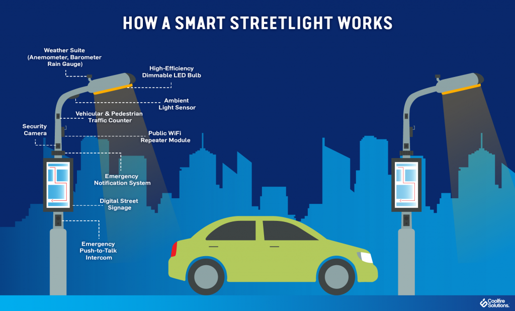
Today streetlights are viewed as an underutilized asset. In the coming years, street lighting poles will be seen as more than fixtures for luminaires, but as outlets for electrical energy and be used for other purposes such as charging electric vehicles, operating WLAN routers and video cameras, as well as hosting sensors. Which is the application space for the LUMAWISE Endurance S connectivity platform. Providing manufacturers with a standard mechanical base to build electronics on to, coupled with a new DALI based architecture this new technology allows for an endless list of connected sensors to be developed. Already entering the market are the more traditional sensors such as photocells and central management systems. This is shortly followed by motion detection, but why stop there? Exchangeable modules could be developed for traffic counting, incident detection, pollution monitoring and for identifying free or occupied parking spaces.

Move Towards Central Management Systems
With an increased use of LED in outdoor applications, local authorities, councils and utility companies will have already reduced their energy consumption. To realize further savings comes a growing need for control of the LED. As a consequence, many luminaire operators are considering moving from streetlights with basic functionalities (photocells) to more flexible Central Management Systems (CMS) that offer more control, better programming, and higher efficiencies. However, this decision to move to a CMS does not need to be made on day one. As LUMAWISE Endurance S modules is a pluggable system, a luminaire can be installed with a simple photocell or even with no control and later extra functionality can be added or replaced. Giving a streetlight a truly 20 years of useable life.

The LUMAWISE Endurance S modules consists of a standardized interface between the receptacle and module base or sealing cap. This uses an integrated single gasket that can accommodate and seal both luminaire and module using the same connection interface for either 40mm or 80mm diameter central management systems. This allows different modules to be exchanged and upgraded in only a few seconds, without having to electrically isolate the lighting pole.

Designed specifically for outdoor LED light sources and drivers, LUMAWISE Endurance S modules has been created as a standalone system and can be used in a complementary function as an auxiliary sensor module when additional functionality is required in ANSI/NEMA based fixtures.

Installation is easy thanks to its simple push-and-twist lock feature which does not require any tools and can be completed using one hand. The LUMAWISE Endurance S modules can be mounted in any direction and offers improved sealing when compared to other systems. Modules can be exchanged and upgraded in only a few seconds without having to electrically isolate the lighting pole.

LUMAWISE Endurance S modules was developed with several partners to ensure a complete system is available, including application specific drivers and control nodes. The partners also collaborated with the Zhaga Consortium. This is a global lighting-industry organization that is standardising components of LED luminaires, including LED light engines, LED modules, LED arrays, holders, and electronic control gear (LED drivers) and connectivity fit systems. Having these standardized components helps to simplify LED luminaire design and manufacturing, and to accelerate the adoption of LED lighting solutions.

Zhaga describes a connectivity fit system for smart outdoor luminaires in what is called Book 18. This is Zhaga’s most recent contribution to the rapidly-emerging world of smart lighting. Book 18 defines a standardized interface between an outdoor LED luminaire and a sensing/communication module that sits on the outside of the luminaire. The module connects to the LED driver and control system, and typically can provide sensory inputs while also communicating with other luminaires in a network.

The focus of developing this new Book 18 specification was to demonstrate the potential of new architecture and new functionalities which can create value for developers, installers and users of outdoor lighting. The standardized interface defined in Zhaga Book 18 enables the installation of future-proofed outdoor LED luminaires, which can be easily upgraded with smart communication and sensing capabilities. Zhaga member companies are already using the specification to develop products that will stimulate the market for smart outdoor LED luminaires.

The development process was relatively short: TE first started work on this in early 2016. Throughout the process, the product developers worked closely with the Zhaga Consortium, which is responsible for developing specifications that enable the interchangeability of LED light sources made by multiple different manufacturers. As a result, the new module now sets a new standard for European outdoor luminaires, providing an alternative or complementary solution to existing ANSI/NEMA product lines.

Categories Lighting

Flicker, Shimmer and Ripple – Lessons in Light Quality

Lighting oscillation characterized by flickering and sometimes shimmering between on and off is universally a bad experience – to consumers, lights should be either on or off. The human eye easily detects low-frequency oscillation in output light amplitude (intensity). Therefore, lighting designers must attempt to minimize any periodic disturbances below 2x the line frequency (< 100 Hz) to avoid unacceptable (detectable) variations in light output.  

There is some confusion in the market over terms used to describe variations in light intensity, possibly not an entirely accidental state of affairs, so let’s look at what is acceptable and what is not.

Flicker is Not Acceptable – Flicker is a rapid light-dark oscillation of the light source at low frequency. In solid-state (LED) lighting, flicker is typically associated with the misfiring of a TRIAC dimmer when presented with a high-impedance LED driver (dimming will be described in another article). A consumer confronted with a flickering light source, will change that light source.

Shimmer is Sometimes Acceptable – Shimmer is a variation of the light output from a light source. It is also low frequency and varies between almost imperceptible and extremely obvious. Depending on the application and the proximity of other light sources, a certain amount of shimmer may be acceptable to the user.

Low Frequency Components Cause Shimmer and Flicker – All power supplies for solid-state lighting have a ripple component in the output current they deliver to drive the LEDs. Depending on the topology selected, this can be in the order of 1 percent to 100 percent (how ripple is measured will be described shortly). The frequency of the ripple typically comprises 120 Hz or 100 Hz (for 50 Hz AC line voltage regions) and a higher frequency component typically in the 30 kHz to 100 kHz region. It is worth noting that 100 percent ripple is not new in lighting. Low-pressure-sodium streetlights (the yellow ones) typically exhibit 100 percent output ripple as do several types of compact fluorescent tube lamps. Single-stage bulb drivers are by far the most widely used LED bulb drivers in the market today and typically have output ripple current in the order of 30 to 100 percent.


Figure 1. Typical output current and voltage waveforms for an LED driver

The Role of Frequency in Determining the Impact of Output Ripple – In describing flicker, shimmer and ripple, both amplitude and frequency were described. The frequency of the variation in light intensity is critical because the human eye is extremely sensitive to low frequency variations but quickly becomes insensitive to variations above 100 Hz. LED drivers are designed to eliminate very low frequency ripple, in the sub 100 Hz range. Asymmetric TRIAC operation in deep dimming is one example of a condition that can cause obvious shimmer when TRIAC dimming – it is readily noticeable because of its 50 or 60 Hz operating frequency.

100 Hz and 120 Hz ripple is not easily seen by most observers. Even so, various lighting standards and guidelines regulate output ripple in order to limit secondary (stroboscopic) effects and to further reduce the likelihood of noticeable shimmer. In addition, some LED manufacturers are reluctant to publish limits in the amplitude of the ripple current that their LEDs will tolerate. Very high ripple values can reduce the average current that an LED string can pass without exceeding maximum current limits – reducing the effectiveness of the LEDs and increasing cost.

How Ripple Current is Measured and Specified – While it is not a perfect match, the variation in light intensity provided by LEDs in a light source closely follows that of the current used to drive them.

LED-driver specifications typically describe the acceptable ripple as the ratio of peak-to-peak current as a percentage of the average current. Energy Star has opted to prescribe Flicker Index in its guidelines.  Flicker Index is the ratio of the light output above and below the average in one cycle. Japan also has a limit for output ripple (the Denki-Youhin-Anzenhou – Safety requirement for Electrical equipment) that requires the minimum output current to be more than 5 percent from maximum output current; frequency of ripple must be ≥100 Hz. Japanese customers often opt for very low ripple current designs to meet the required specifications of local LED manufacturers.

How to Reduce Ripple Current – Increasing output capacitance will reduce ripple current but space is often limited and additional capacitance is expensive.  Another alternative is to use a linear regulator that can smooth out the peaks in the ripple current. While this is extremely effective, the linear regulator components do add a cost burden and reduce the driver efficiency by up to 6 percent (see Table 1). Figure 2 shows an Active Ripple Current Filter (ARF).


Table 1. Active Ripple Current Filter (ARF) efficiency


Figure 2. ARF diagram

Active ripple reduction circuits can also be used – the LED driver detects and compensates for the reduction in output current associated with the rectified AC line cycle. These circuits can reduce ripple by a small amount without the bulk of electrolytic capacitors, but they significantly reduce power factor.

Wonderful Technicolor – Once the designer has managed to keep the lights on without variations in intensity, they next have to focus on the quality of the illumination provided. Features such as color temperature have some regional variability (Northern climates tend to prefer cooler colors), and the Color Rendering Index (CRI) becomes important, especially when the lighting environment is to be used to view something. We will look at the meaning of terms including Color temperature, CRI and MacAdam ellipsis next month in the second half of this article.

Categories Lighting

Global LED Lighting Trends Reveal Significant Growth and Product Development

The outlook for the LED lighting market remains very bright. Despite fluctuations in the economy and the general lighting industry, LED lighting continues to occupy a significant portion of the overall lighting market. In fact, a November 2014 article in LEDinside, a research division of TrendForce, has projected that LED lighting market penetration will reach 31 percent of the $82.1 billion global lighting market in 2015. LEDinside also reported that Europe is the largest geographic market segment—accounting for 23 percent of the global lighting market share, followed by China at 21 percent and the US at 19 percent. Industry analysts predict significant growth over the next decade.

Product development managers and electronics engineers in the LED lighting market strive to continue growing right along with the industry trends. To succeed in developing LED designs that flourish in the current market, however, they must incorporate reliable circuit protection technologies that deliver a strong return on investment (ROI).

This LED market report reveals the present state of the market, trends for several LED segments and projections for global growth. It highlights the need for industry-leading circuit protection solutions from a reliable manufacturer and specifies the ideal protection devices for several LED applications.

Present State: LED Market is Shining Bright
Recent statistical data supports the pivotal position of LED technology in the global lighting market. Global LED lighting market penetration is expected to reach 31 percent in 2015, according to a recent article from LEDinside. In addition, LEDinside has reported that the global commercial LED lighting sector will reach $26.7 billion in 2015.

Some of the most common applications for LED lighting are outdoor, residential and architectural. Outdoor LED lighting is quickly gaining popularity for tunnels, roadways, traffic lights, parking lots and garages. According to Strategies Unlimited, 2013 revenues for outdoor LED lighting were $0.7 billion. The firm also reported that nearly two million LED luminaires were installed in tunnels and roadways in 2012. IHS Technology stated that out of the 140 million streetlights installed worldwide in 2013, 19 million of them were LEDs (Source: Forbes).

Residential applications for LEDs include lighting in kitchens, hallways, dining rooms and bathrooms. When compared with other lighting technologies, only LED lighting can be used as a comprehensive replacement for fluorescent lighting (Source: LEDinside). LEDs can be used in multiple rooms throughout the home, are available in several varieties and offer a technology that is relatively easy for consumers to learn. McKinsey’s 2012 lighting market report revealed that residential is the largest general application segment for LED lighting. In 2011, it represented almost 40 percent of the general lighting market.

According to MarketWatch, the architectural segment is the second-largest end-user segment for LED lighting. For architectural applications, LEDs are used in both decorative and functional lighting. Decorative LEDs are used to illuminate fountains, pools, gardens and statues. For functional applications, including building facades and landscaping, LEDs provide visibility and enhance safety on residential and commercial properties.

In response to the current LED market trends, manufacturers are making significant changes in their operations. IHS reported that manufacturers are placing a greater emphasis on vertical integration, focusing on chip-on-board modules and light engines in 2015. Moving down the supply value chain to products that form the intermediate steps between LED components and lamps/luminaires may be an attractive strategy due to the low-profit margins for LED components. Both Phillips and Siemens, top players in the LED lighting market, have separated their lighting work from their core business to enable faster response-to-market dynamics and to achieve higher profitability. In addition, GE has taken steps to start producing its own LED circuit boards and may spin off its lighting business in the future.

Future Promise: LEDs Light the Way to Outstanding Growth
Forbes has predicted that the LED market will continue to grow throughout the next decade, with the global LED market share reaching about 70 percent by 2020. According to McKinsey, Asia will occupy about 45 percent of the global general lighting market by 2020. The report indicated that rapid penetration in Japan and China is driving Asia’s market-leading position for transitioning to LEDs in general lighting. In Europe, the current LED value-based market share is approximately 9 percent, McKinsey reported. By 2020, the share is expected to rise to over 70 percent.


Figure 1. The global growth of the outdoor LED market is self-evident as cities around the world adopt LED lighting. London (pictured above) announced the largest street modernization project with plans to replace 350,000 of the 520,000 city streetlights with LED lights by 2016.

Outstanding growth is projected across various LED market segments, including residential and architectural. Forecasts for LED growth in the residential segment are almost 50 percent for 2016 and over 70 percent for 2020, according to McKinsey. For architectural lighting, MarketWatch revealed that Japan and Europe are the fastest-growing regions. McKinsey has predicted that architectural lighting will remain the early adopter for LED lighting, with its market share reaching almost 90 percent by 2020.

The outdoor lighting industry is also expected to grow at a rapid rate. Strategies Unlimited has forecast that the global outdoor LED lighting market will reach $1.9 billion by 2017. The organization has also predicted that LED street light installations will grow by 400 percent over the next five years. According to Semiconductor Today, the market share of LEDs in street lighting worldwide will grow from 53.3 percent in 2014 to 93.8 percent in 2023.

Safeguard ROI: Circuit Protection for LED Lighting Innovation
Electronics engineers and product development managers are continually innovating LED designs to keep pace with the latest market trends. Creating designs for LED lighting applications presents several challenges, including the need to protect the LEDs’ electronics and circuits from lightning, transient surges and electrostatic discharge (ESD). These electrical threats may jeopardize the safety of personnel and endanger the consumer’s ROI. Failure to use proper safeguards could also lead to compliance issues with regulatory and safety standards related to overvoltage transients.


Figure 2. Outdoor lighting applications have a much better chance of delivering their full ROI with the proper implementation of surge protection devices (SPD) such as the LSP05-LSP10 Series from Littelfuse.

Circuit protection technologies are vital for safeguarding the vulnerable electronics and circuits within LEDs. To prevent LED lighting from experiencing failures within an investment payback period of about five years, high durability and reliability are essential. Before selecting a compatible circuit protection device, it is important to find a manufacturer who understands LED lighting industry standards and the safety issues associated with designing LED retrofit lamps and outdoor luminaires.

As the global leader in circuit protection, Littelfuse recommends protection devices for LED driver and power converter circuits used in a variety of lighting applications. Littelfuse manufactures a variety of fuses, varistors, surge protection modules (combination of varistors) and TVS diodes for LED lighting applications. To ensure compliance with industry standards and reliability, the company performs extensive product testing.

The following table indicates the ideal circuit protection device for several applications:


Table 1. Circuit protection solutions for LED lighting applications.

Conclusion
According to industry experts, the global LED market is experiencing rapid growth across several applications and will continue to grow throughout the next decade. In response to this growth, the demand for high-reliability circuit protection technologies will continue to increase. Circuit protection is needed to safeguard sensitive LED electronics and circuits from electrical threats and meet industry standards for safety and reliability. This technology also prevents LED lighting from experiencing failures within an investment payback period of five years. Fuses, varistors, surge protection modules and TVS diodes are designed to protect LED applications and maximize the lighting investment.

Categories LED

Diving into Benefits with LED Luminaires in Natatorium

Pool Lighting – Indoor pools are hard on light fixtures. The exposure to a warm and humid environment is particularly challenging. Additionally, because natatorium fixtures are difficult to access, maintenance must be kept to a minimum.  If any fixture’s or lamp’s glass were to fall into the pool during maintenance, the entire pool needs to be drained – an expensive and time-consuming effort.

Life safety and accident prevention are the driving forces behind natatorium lighting. Because water is a reflector, reducing the glare from the fixtures is critical.  Adequate light levels, bright illumination, and consistent uniformity are also very important.

Fixtures for this application need to be at least damp location rated, offering the highest safeguard against moisture and water treatment chemical vapors. 

One way to address all of these issues is through the installation of LED luminaires.


Waukesha South High School Natatorium | Waukesha, WI
South High School is Waukesha’s oldest high school, opening in 1957. Today, the 1,460 students use a swimming pool complex that was rebuilt in 2005, replacing a smaller and much older pool, spectator and locker room facility. The current natatorium is larger than in most schools, measuring 25 yards x 30 meters and the oversized perimeter accommodates nearly 2,000 spectators.

The 27,000 square-foot natatorium is used extensively by the high school physical education department, the school’s swim team and the Waukesha Express Swim Team.

Lighting – The complex was originally designed with a metal halide (MH) indirect lighting system to reflect light from the ceiling to minimize glare on the water’s surface. Over the years the ceiling and walls darkened due to deteriorating light levels and fixtures burning out, creating a cave- and dungeon-like atmosphere. Replacing the burned out fixtures was so challenging, they were typically left until there were enough to warrant bringing out the lift.

Tom Cherone, master electrician Waukesha School District, knew the lighting system needed improving:

  • spectators were complaining they couldn’t see the swimmers because the lights were so dim;
  • the low light levels were a safety issue for the lifeguards;
  • he was worried while conducting maintenance on the MH fixtures that if glass dropped and broke in the pool the 480,000 gallons of water would need to be drained;
  • and MH technology requires 10-15 minutes of “cool down to relight,” meaning that the bulbs needed to cool down enough before they could be re-lit again, which was very inconvenient.

Through Wisconsin-based Hein Electric Supply, which has a long-time relationship with Waukesha School District, Cherone learned about retrofitting the existing lighting system with LED high bay luminaires to improve illumination quality, safety and security while also reducing energy costs and consumption.
Recently, in a one-for-one replacement, 42, 1000-watt MH fixtures were replaced with 240-watt LED high bay luminaires and eight, 36-watt florescent tubes were retrofit with 80-watt LED high bay luminaires.

“The new lights are terrific,” said Cherone.  “They strike instantly, provide more lumens than our old MH lights, will last for years and are cost effective.”  “When all the fixtures are on we’re saving an astounding 70 percent in energy over the previous MH lights,” Cherone continued.

Because they emit far less heat than MH fixtures, the school will be able to run the air conditioning less in the summer months, further reducing the energy bill.

Additional power savings are achieved from turning off the fixtures when not in use. The previous lights were left on continuously because they took so long to warm up to full brightness.  These LED luminaires light immediately, eliminating the need to have them on all the time.

“At swim meets I used to apologize to the visiting teams because it was so dark,” said Blaine Carlson, CEO/head coach Waukesha Express Swim Team. “Now, with these new lights, I think we can even attract additional meets to this facility,” Carlson continued.

Cherone is so pleased with the reduction in maintenance, energy savings and consumption, and the dramatic improvement in light quality that he’s planning to replace all of the MH lights in the district schools’ pools with LED high bay luminaires.

In addition to upgrading the natatorium lighting, the district is implementing an exterior lighting program for the schools’ parking lots; saving the district more money and, most importantly, improving security through better  light levels.

Categories LED

Dinosaurs Luck Out with LEDs

In the days of old when Knights on horseback hunted dinosaurs by flashlight, electrical safety regulations were a much simpler affair. Incandescent light bulbs were installed in metal luminaires with a bit of Bakelite here and there for insulation. To make everything safe the electricity supply incorporated a fuse while an earth wire kept the metalwork at ground potential.

Then along came plastics, double insulation, residual current circuit breakers, fluorescent tubes, dimmers, and now switch mode power supplies and LEDs. To accommodate all these changes the regulations were expanded and improved.

Unfortunately, modern technology moves faster than regulation can keep up, and in the case of LED lights there is confusion as to what is appropriate and applicable.

From an electrical perspective LEDs are incredibly safe: They operate at only three volts DC, so you need a resistor to actually decrease the voltage before you can use an LED in a three cell flashlight. It also means that to operate most types of LED from the utility supply requires a power supply. These range enormously in sophistication. At one extreme it can comprise a bridge rectifier and with a capacitor used as a reactive dropper. These are common in the types of cheap LEDs bulbs you might commonly find online, where the phrase “caveat emptor” seems highly appropriate. What should be present is a properly designed switch mode constant current power supply with over voltage, over temperature, spike suppression, short detection and other protective circuits.

In an application like domestic lighting, white LEDs need to be in the 5 to 10 W power range to compete with incandescent bulbs on a Lumens basis. Because LEDs are relatively inefficient, albeit miles better than incandescent bulbs, they have to be soldered on special metal-in-board PCBs to dissipate the heat produced. The PCB connects to a heat sink, which will often be accessible as the fins need to be in fresh air to provide cooling. The question then arises: How much dielectric isolation does there need to be across the metal-in-board PCB between the finger-accessible metal side and the electrical tracks connecting the LEDs to the power supply?

There are roughly 50 standards potentially applicable to LED lighting and many are still in development. Not only is there potential uncertainty over which standards are applicable, but standards are also complex documents that are written in carefully constructed English. There is good reason for this – they are intended to cover all conceivable scenarios within a precisely defined scope. Yet to an LED engineer (having a casual flick through in search of design guidance) they sometimes might as well be written in Latin.

I asked a few people in the industry how much dielectric isolation they thought was required for metal-in board PCBs used in LEDs. Unsurprisingly, the answers ranged from “50V” through “it depends” to “over 5kV”.

Making the correct choice matters because both the breakdown voltage and the thermal resistance between the LED and the heat sink are proportional to the thickness of the dielectric in the metal-in-board PCB. Keeping LEDs cool is important for sustaining their hue, brightness and longevity and also to maximise efficiency. Using a Nanoceramic for the dielectric means this layer can be extremely thin to provide good cooling yet with sufficient dielectric potential to ensure the product will be electrically safe.

Because electrical safety is of huge importance interpretation of the standards, and from there the dielectric potential of the metal-in-board PCBs, should always be left to those that are experts in the field.