Categories Lighting

Controlling Standby Power for Smart Lighting in Consumer Applications

Smart lighting is characterized by the sophistication in lighting control that has grown with the emergence of LED-based lighting. In fact, smart lighting is not practically achievable with traditional incandescent light sources and it is not as common with fluorescent light sources either.

To clarify: it is possible to control incandescent and, to a lesser extent, fluorescent light sources using phase-cut TRIAC dimmers and occupancy sensors. The driver circuits required for LED light sources, however, are more suitable to the low-voltage analog and PWM signals that are most readily associated with microprocessor control. But bringing the bulb within the control of a computer system opens up many other possibilities: power waste can be reduced; the user experience can be enhanced and the light source can even be used for data transfer. The challenge for smart lighting is to make use of all the functions afforded by computer control without losing efficiency – since efficiency was the reason the world looked to LED in the first place.

While commercial applications have already begun to adopt smart lighting, consumer applications are often tied to bulb-sized lighting nodes with low-power consumption, which makes the quiescent power consumption of the controller more of an issue. Consumers are unlikely to re-wire their houses simply to accept a hard-wired lighting system such as Power over Ethernet, Emerge etc., so most of the consumer-facing products in the marketplace today rely on wireless communication protocols (ZigBee, Z-Wave, Bluetooth or BLE, for example ) to control the lamp.

A 60 W A19 lamp today uses perhaps 7.2 W and is around 90 percent efficient – drawing approximately 8 W from the AC supply. ENERGY STAR suggests that the average bulb is on for less than three hours per day. The control electronics have to be on all the time, scanning for a start-up signal that will turn the bulb on. One popular smart-dimmable consumer bulb cites 0.45 W consumption in standby. If we ignore the power used by the base station (a base station can control 50 lamps), it means that the power consumption of the most common LED bulb is increased by around 50 percent by adding smart controls.

The ENERGY STAR Lamp Specification – Version 2.0 (Draft) has a section on standby power for connected lamps, with recommendations from various groups. 0.5 W has been proposed as a starting point. Several groups are pushing for a higher power level (>1 W was suggested during a recent presentation at Strategies in Light 2015).

This problem will get worse over time as LED conversion efficiency continues to increase (and therefore the power drawn by the lamp for lighting decreases).


Figure 1. DER-227(2) A 3 W power supply showing 70% conversion efficiency at 150 mW (0.3 A) output

How much power is required for a Wi-Fi transceiver?
The International Energy Agency (IEA) recently produced a report(1) which showed Wi-Fi transceiver standby/idle power use as being between 0.004 and 0.13 W. At this power level, power-supply conversion efficiency can be expected to achieve perhaps 70 percent (see Figure 1) suggesting a power budget of <200 mW would be achievable (and reduce control power to approximately 15 percent of the total power in the above example).

Smart technology for consumer LED bulbs and luminaires offers opportunities to fundamentally change how we use and experience light within the home. The benefits are significant but the fundamental benefit of energy saving must not be forgotten in the search for the limits of that new functionality.

Categories Lighting

The March of Mid-Power LEDs into General Lighting

The research firm IHS just released a 2014 forecast for the LED general lighting market, which indicated that mid-power LEDs would represent >80 percent of the LED units shipped and roughly 48 percent of the revenue.  This is quite a change from a few years ago where revenue of high power LEDs dominated the general LED lighting market. There are numerous factors that have driven this shift including improved LED efficacy, adoption of lower cost plastic packaging, and a shift from magnetic transformers to mechanical approaches to achieve safety isolation.  This is especially true in integral bulbs and as a result the LED string voltage is no longer limited to 30 to 60 V depending on the regional safety requirements.

In some cases mid-power LEDs are a combination of several low power LEDs in series in a single package.  As a result, high voltage mid-power low current LEDs are available with typical forward voltages ranging from 9 to 100 V. One impact of using these LEDs is that alternate driver topologies instead of the classical isolated flyback can be used that result in lower electronics cost and/or higher power conversion efficiency.


Figure 1. Single LED string direct AC drive operation

One of the simplest direct AC approaches involves a bridge rectifier, constant current regulator (CCR) and a string of LEDs as seen in Figure 1. If the LED string voltage is sufficiently high compared to the input AC voltage, the losses in the CCR can be kept to a reasonable level while achieving > 0.9 power factor.  This approach does have lower LED utilization since for a portion of the AC cycle, no current flows through the LEDs as seen by the red line.  In this example there is no electrolytic capacitor in the circuit for energy storage so this type of driver results in 100 percent optical flicker at 100 / 120 Hz (2x the AC line frequency) but the driver circuit is simple, small and can have a long operating life time.   As it is not always practical to match the LED string voltage to the AC line voltage a switching topology is needed.

To better understand how to determine the right switching topology based on the string voltage, we wanted to compare several mainstream topologies and provide some general guidelines to help designers understand how the selection of the LED string voltage impacted the topology choice.  To do this a figure of merit (FOM) was created that combined the maximum voltage stress and peak current through the power switch as a function of the LED forward voltage and the input line voltage.  This FOM is a good proxy for both efficiency and cost in a switching LED driver as the lower the peak current, the lower the losses in the switch, inductor and diodes.

Two general use scenarios were considered. First, applications where high power factor and low THD (<20 percent) were required and the second where high power factor is not required.  As an example for ENERGY STAR LED lamps, there is no power factor requirement for lamps < 5 W and in the EU there is a special input line harmonic exception in EN61000-3-2 for lighting products < 25 W so high power factor is not required.  An added benefit of not needing high power factor is that it is easy to achieve low optical flicker.

The buck, buck-boost, boost and isolated flyback with a turn’s ratio of 3 were all compared based on the FOM (the lower the better) as a function of the VF to Vin peak ratio.  In the case of the high power factor case, the total harmonic distortion was limited to < 20 percent for analysis and we assumed a 600 V MOSFET (80 percent derating).  For VF/Vin ratios from 20 to 40 percent, the power factor corrected buck is the best topology. The upper limitation of the buck is related to THD and power factor and not stress on the power switch.  Interestingly it turns out the best topology from the FOM analysis is the boost, which is not the first topology to come to mind for many designers.  An example of a complete high PF 10 W boost design is shown in this design note where a 220 V LED string was driven at 30 mA across an input voltage of 90 to 135 Vac.


Figure 2. Topology comparison for high power factor >0.9


Figure 3. Topology comparison for low power factor (EN61000-3-2 Class C Exception)


When looking at applications were it is not critical to achieve high power factor, the clear winner for strings of higher voltage LEDs is the buck topology as seen in Figure 3 as it has the best FOM across a wide range of forward voltages.  An added benefit of this approach is that it is one of the simplest to implement and can have low optical flicker. The reason that the curve ends below 70 percent is due to meeting the requirements of the EN61000-3-2 Class C exception where the input capacitor is undersized to control the input current shape. For applications in the US market where compliance to EN61000-3-2 Class C is not required, this range can be extended. An example of a complete 3.8W buck design is shown in this design note where a 150 V LED string was driven at 25 mA across an input voltage of 200 to 265 Vac and achieved 85 percent efficiency.

This FOM comparison is a good reference tool at the beginning of the LED selection and architecture definition.  In some cases, especially at more narrow VF/Vin, there are several options that should be considered since the differences between different topologies is relatively small but in many cases this can give clear guidance in what topology is best for lowest system cost and better efficiency.

Categories Lighting

Collaborative Approach Addresses Next Generation LED Lighting Design Challenges


The accelerating transition to LED-based lighting is changing the dynamics of luminaire design. Traditional approaches in which components are evaluated separately to arrive at an optimal BOM are being replaced by more synergistic, system level thinking. Several trends are driving this evolution in system design, which is supported by greater collaboration between providers of LEDs and power electronics components.

The first trend is the emergence of many new competitors, concurrent with rapidly falling prices for LEDs. While LEDs historically represented a large portion of a fixtures’ cost, other electronic components – including driver, power stage ICs and LED protection devices – are becoming a more significant portion of the overall BOM. And of course, there is relentless pressure to reduce the total end product cost.

Another major trend affecting the industry is increased demand for energy efficiency. This is best addressed by a system level approach and not by focusing solely on component selection. To respond to the efficiency challenge, the on-going migration to digital control of driver ICs and power stages for LEDs provides fixture designers with much greater ability to optimize power conversion.

Lastly, as LED-based luminaires become pervasive across multiple segments and different lighting sub-applications, there is enormous pressure to simplify the design process. To best address the widest number of market opportunities, fixture designers need to shorten development cycles. This is addressed by the emergence of simple and easy-to-integrate LED and power modules that reduce the level of complexity in design of the lighting element.

The flexibility to drive LEDs at different drive currents and different configurations, thus forming luminaires in different shapes and sizes than possible with traditional light sources, provides an opportunity for disruptive innovation in lighting. Yet this flexibility poses unique challenges for driver design. Until some level of standardization takes hold, each individual design requires custom drivers. The relative immaturity of control schemes related to dimming and other feature requirements can make driver design overly complicated and expensive. The application itself poses several challenges, whether it is outdoor wall-washing lights, or indoor down-light solutions driven from AC mains or from a DC bus or power-supply.

With these concerns in mind Infineon developed .dp, a Digital Power 2.0 generation of digital and intelligent LED driver ICs used in combination with state-of-the art power stages. The internal structure of the controller is built around a programmable Digital Signal Processor core, combined with optimized power-management and protection peripherals (Figure 1).


Figure 1. High-level digital LED driver IC architecture

High level integration as well as programmability offers several advantages, beginning with flexibility. Designers can employ several different drivers at different drive currents, and take advantage of features such as support of 0-10V interfaces and DALI interface compatibility. The LED driver can handle AC mains variants as well as DC input voltages in several different topologies such as boost, buck, fly-back, etc. Designs can easily be adapted through firmware changes, supporting fast time-to-market for variants of an original design for product line or market segment extension. Diagnostics and command-and-control (e.g. read out sensors, NTS, etc.) are greatly improved due to the digital nature of the part. Advanced controls support time based correction to prevent lumen degradation of a fixture and temperature compensation during color mixing to obtain desired colors or tunable white light. Fixture designers can add customized control code to support unique features, with the added code protected from reverse engineering efforts by security features that prevent readout of memory content.

With continued evolution of designs and manufacturing advancements, LED components will continue to increase in efficacy and light output. Manufacturers such as Philips Lumileds continue to innovate in response to the dynamic demands of the market. The vast selection of options and the introduction of more and more application specific LED components offer luminaire manufacturers multiple opportunities for innovation in such areas as energy consumption, light output, and lifetime claims to name only a few.

Let’s take the example of LED-based downlight fixtures. In the recent past, downlights were mostly constructed with a serial string of high-power LEDs, which meant relatively high drive current at relatively low forward voltage. Some manufacturers evolved this design by adopting CoB (Chip on Board) solutions with various current/voltage configurations depending on the serial/parallel configuration of the particular product. Today it is possible to construct downlights using an array of mid- or even low-power LEDs, introducing yet another long list of configurations and options. In all cases, the traditional design approach for these solutions quite likely involved re-design of the LED driver. This introduces cost and time-to-market complexity in terms of establishing design reliability, and conforming to fire and safety regulations around the globe. This complexity is eliminated with newly available, second generation digital power and power stage devices. Reconfiguration now is managed by simply re-programming the DSP based system to provide optimal efficiency at many Vf/If configurations.

Another example would be a luminaire manufacturer’s effort to expand across market segments, say from residential to professional and even industrial applications. While system geometries may be similar, retail price, light output performance or warranty requirements may be different. To address each segment successfully, it is desirable to minimize the number of fixed system sub-components and have the ability to simply change operating parameters. Taking the previous example of the downlight, let’s compare a residential with a professional solution. The usage profile in a private residence is completely different compared to a hotel hallway. The residential user is mostly interested in the initial cost to purchase whereas the hotel manager focuses on total cost of ownership. In this scenario the luminaire manufacturer may choose two different light engines – one low cost, the other high efficacy and high reliability – which usually require different driver configurations as well. With a programmable base product, the same driver subsystem with the appropriate firmware can be deployed to satisfy both scenarios with minimal design and qualification effort.

Yet another value of DSP-based programmable LED driver sub-systems is end of line calibration. Consider a luminaire that is exchangeable with its own kind, but due to uniformity reasons can’t differ from others in light output over its expected lifetime. In retail store lighting, where merchandise is illuminated by highly specialized lamps and luminaires, it is essential that newly added or replaced light sources have the same visual output as those already installed. There are two factors to consider in this case. First is the light output degradation over time. This can be compensated for by ever so slowly increasing the drive current based on either a pre-programmed or default current compensation curve, or by custom compensation patterns based on specific applications or needs. Secondly, as LED components keep improving in efficacy later versions of the same luminaire may require less current to achieve the same light output. At the same time lower currents mean lower stress and aging which in turn will have an impact on the long term lumen output stability – hence the light output compensation algorithm may need to be slightly adjusted as well.

In conclusion, market trends and the wider adoption of LEDs pose new challenges and open the doors to new market opportunities in the lighting industry. The trends include increased pressure to reduce system costs, the continuous increase in demand for energy efficiency and growing complexity of system design. To address these needs, the industry requires solutions to drive the LEDs that are flexible and that enable modular designs. The flexibility enabled by parameter setting or firmware changes can be leveraged at different stages of the product development or at different stages of production flow. Advanced controls such as time based correction, temperature compensation or end of line calibration can be implemented either through predetermined characteristics curves of LEDs or by sensing relevant parameters at the application level. Lighting designers should look to both LED and driver-IC manufacturers for components and modules that support a system level approach. This will allow them to take advantage of the full potential for innovation that LEDs bring to lighting at different levels of the supply chain and ultimately in the hands of the final customer.

Categories Lighting

Evolution of Flexibility in Lighting

In the early years of solid-state lighting, manufacturers focused on ensuring LED luminaires and sources were first and foremost good illuminators. Manufacturers focused on efficacy, reliability, color and luminance. These early LED solutions were designed to behave and look like the traditional products they were replacing. As LED lighting matures, the focus is shifting toward designs that leverage the extraordinary flexibility of the LED. 

LEDs are semiconductor light sources that can be controlled like any other electronic components. The ability to control the LEDs, coupled with their inherently small size, opens the door to endless flexibility in lighting designs and features. For example, the lighting industry has seen an abundance of products with new dimensions of control such as intensity and color tuning.

While important, changing the hue and color temperature of lighting are not the only desired features to control. A critical dimension of light output control is the spatial distribution. Where the lighting is aimed, the beam shape, angles, and distribution are critical parameters.

What architects and designers really want is the ability to put bright white light exactly where they want it to create a perfect design. What owners really want is the flexibility to easily change that distribution as space needs change.

In multifunctional and reconfigurable spaces—such as retail shops, entertainment, hospitality, meeting rooms, museums, galleries and residential spaces—focal points and tasks can change frequently, so flexibility in the light distribution is valuable. A growing number of spaces are joining this category, such as modern classrooms and offices.

Even with the most advanced LED solutions, it was relatively difficult to change the pattern of light. For example, in a retail shop a typical solution is to use track lighting to complement the general lighting. This requires the addition of an accent lighting layer with appropriate luminaires. Each time the space changes, the track lighting must be re-aimed. The typical approach is to do this on a ladder, though some manufacturers offer motorized luminaires. This is labor intensive and expensive.

Using aimable lighting, we can direct the light where we want it, but the beam angle is fixed. Since objects and tasks not only change in terms of location but size and shape, the ability to adjust the light pattern becomes important. The industry responded with adjustable optics. This allows designers and owners to adjust the beam spread within a defined range, again using a ladder to individually access each luminaire

OSRAM SYLVANIA talked to designers, architects, retailers and specifiers about the flexibility they need to easily control lighting.  We attempted to address these different needs in a single LED innovation.

This new luminaire is extremely flexible.  Light intensity, beam shape and angle can be simply and easily controlled remotely using a wireless Android app.  The app allows the user to take a picture of the space using a wireless camera and then touch the image on the screen to aim light. Lighting conditions can be tuned and transformed instantaneously without the use of a ladder.

The recessed luminaire, called OmniPoint, consists of an array of LEDs that are focused through an aperture about the size of a five-inch downlight. Each LED is individually controllable enabling a virtually unlimited number of light patterns. The luminaire can provide ambient and accent lighting at the same time, which can be directed almost anywhere in the space in real time.  This flexibility may reduce the overall number of luminaires that are needed in the space resulting in a clean ceiling look.

This LED innovation is the result of natural evolution marrying new technology with longstanding professional lighting needs. At the recent LIGHTFAIR International 2015, it was recognized with an Innovation Award for the Most Innovative Product of the Year and also won the Innovation Award in the Recessed Downlights category. You can see it in action here.

Smart, connected LED lighting solutions that allow us to easily adjust parameters such as intensity, color temperature, hue, beam shape, angle, and distribution are rapidly emerging. These solutions are redefining how we think about, design, specify and use lighting everywhere.

Categories Lighting

Increasing LED Lighting Applications with Heatable Glass Lenses

In my last article, I reviewed examples and case studies on how glass (as luminaire lens material) can be successfully employed in various LED lighting applications to both optimize lighting efficiency and economic paybacks (ROI, TCO, etc.) in standard operating environments (i.e., temperatures > 32°F and 0°C).  In this article, the final entry in this series, I’m going to discuss ways in which a fabricated conductive/heatable glass lens can enable LED lighting to be effectively used in extreme environmental conditions that, to this point, have represented a hurdle towards wider market adoption.

LEDs offer high levels of flexibility and customization (output levels, color temperature, etc.) for lighting applications and, as such, have been and will continue to be adopted in almost every lighting market segment (as shown in the following diagram from the McKinsey Global Lighting Report of 2012).


As you can see, most areas in lighting are quickly migrating towards LED technology.  However, three segments seem to be lagging slightly behind:  Office, industrial and outdoor.  For office lighting, this can be rationalized by the still highly competitive position (in price and energy efficiency) of fluorescent (linear and compact) technology for this market.  For industrial and outdoor, though, there is a different roadblock stagnating LED adoption and that is simply the environmental conditions where these lighting applications operate.  In industrial and outdoor lighting applications, luminaires are seeing extreme weather conditions ranging from extreme hot to extreme cold (i.e., temperatures < 32°F and 0°C) with rain, snow, ice and hail exposure. These conditions, as you will see, prove to be an inherent problem for LED-based lighting.

In traditional outdoor lighting technology like Incandescent and  High-Intensity Discharge (HID) high levels of Infrared (IR) energy (see spectrum below) or “heat” are generated by the light source itself.


Diagram courtesy of Guardian Industries

With this IR heat comes higher energy consumption and lower levels of efficiency/efficacy, which has allowed LEDs to become a more-attractive technology long-term.  However, the absence of this IR heat generation from LED lighting vs. Incandescent and HID technology (as shown in the following output spectra) makes it difficult to use LEDs in lighting applications where it is necessary to remove snow and ice from the lens surface – such as outdoor and industrial.


Diagram courtesy of Guardian Industries Corp.

As you can see, the LED output is highest in the visible range and low in the Ultraviolet (UV) and Infrared (IR) ranges of the spectrum.  This means great visible light quality and low levels of UV damage and heat being generated which is good in terms of safety and efficiency.  However, this is bad news when you need that IR energy to remove snow and ice from your luminaire, which is “built into” HID light sources.  This issue has limited the market space potential for LED lighting in outdoor and industrial lighting applications.

LED luminaire OEMs have a number of ways to resolve this problem including:

  • Redirect heat from the heat sink into a cavity in the area between the light source and lens;
  • Integrated a conductive laminate interlayer (tungsten “wiggle wire”) on the lens;
  • Integrate a conductive coating on to the lens surface itself.

Let’s now assess each of these options. The redirection of the heat from the heat sink into the optical cavity is an easy fix but compromises the lifetime of the LEDs junction (one of its major commercial advantages).  Integrating a laminated conductive interlayer is another easy fix but increases luminaire cost and weight and compromises optical integrity and clarity.  Putting the heat directly where it needs to go, on the lens, clearly makes the most sense for LED lighting applications.

Now the question is on the lens material itself to use to accomplish this.

  • Plastics (PMMA Acrylic, Polycarbonate, etc.) are commonly used in LED luminaires but have limited ability to conduct heat or survive long-time exposure to it without degradation.
  • Glass is a proven material in this regard with its ability to be thermally stable > 1,100 °F and 600 °C.

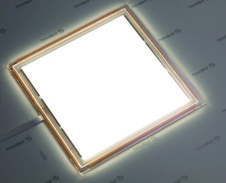
By using a Transparent Conductive Oxide (TCO) coating on glass, we can provide a highly transparent yet conductive (15 – 20 ? /square) lens surface to create heat but still maintain high levels of optical efficiency (> 85 percent) with long-term thermal stability (because the coating itself has seen stable > 1,100°F and > 600°C in the tempering process).  The electrical interconnection can then be easily made through silk-screening buss bars with a conductive paint (such as Ag) onto the surface which are fired into the TCO coating during the tempering process.  By adding an Anti-Reflective (AR) coating, which has been covered in my earlier articles, you can raise the efficiency to > 90 percent.  The following diagram shows the configuration of such a fabricated monolithic heatable glass lens component.


Diagram courtesy of Guardian Industries Corp.

This monolithic heatable glass configuration would provide the following optical performance vs. traditional TCO technologies (Pyrolitic Fluorine Doped Tin Oxide) allowing for > 90 percent optical efficiency in the visible to be met with a single monolithic 5 mm glass lens while providing a conductive surface to heat the glass up to > 200°F (100°C) in temperatures down to -67°F (-55°C).


Diagram courtesy of Guardian Industries

In terms of heating the glass with this TCO coating, the following parameters and options are available for consideration and customizable during the luminaire design stage:

  • Input Power/Supply Voltage up to 100 V AC/DC
  • Operating Power Density range of 0.1 to 9 W/in² which, in consideration, with the following other attributes will determine the maximum surface temperature and heating ramp rate:
    • Input Power/Supply Voltage
    • Surface Area and Shape (rectangle, square, circle, etc.)
    • Terminals (Buss Bar) Size and Distance/Location
  • Electrical and Mechanical Interconnects
    • Terminal/Wires
    • Toggle Pins
  • Manual or Automatic Heating
    • Manual:  Simple ON/OFF control
    • Automatic: Thermocoupler with Feedback Loop

Last, because this heatable glass lens is tempered glass, it enjoys all the historical benefits associated with glass lenses that I mentioned in my first article including mechanical durability, chemical durability, environmental durability, and strength/impact resistance while providing the heating function.

In summary, we can form the following key takeaways about the use of a heatable glass lens to optimize optical efficiency for LED lighting in applications in extreme cold environments:

  • It further opens up the available market space for LED lighting into segments like Industrial and Outdoor where extreme environments requiring the melting of snow and ice prevented implementation and adoption;
  • It allows heat, to be focused on the lens area itself which reduces the risk to the lifetime of the LED light source itself;
  • It can heat the lens and, with the addition of an AR coating, can still reach > 90 percent optical efficiency; and
  • It offers a high-level of design flexibility and customization in terms of performance (optical and heating temperature and ramp rate) as well and serviceability (mechanical and electrical interconnections).

This is my final installment for the series on using glass in LED lighting and I’m confident that you will now look at glass in lighting a bit differently now than before. I hope that you will consider using glass as a lens material in LED lighting applications where you need to increase performance and differentiate your luminaires for competitive advantage.

Categories Lighting

Better Materials for OLED Lighting

LEDs have been replacing traditional lighting at a rapid pace, offering longer life times, more efficiency, lower cost, etc. OLED lighting promises to complement LED lighting by offering better color performance, power efficiency, unique shapes and designs, as well as a thin, lower weight and elegant profile. To enable OLED technology in this emerging lighting market, there is a need to replace traditional materials with new, better-performing materials such as silver nanowires.


Figure 1. Image of Silver Nanowires at 70° tilt

Silver Nanowires
In an OLED device, the top electrode is made of a transparent conductor and plays an important role in light transmission/efficiency. A transparent conductor made of silver nanowires allows for high conductivity with excellent transmission and acts as the top electrode/anode in the case of an OLED lighting system. Silver nanowires in the top electrode are used in the form of a network of wires (see Figure 1) that are a few nanometers thick and a few micrometers in length. With silver being the best conductor on the planet, the network of overlapping nanowires offers conductivity less than 10 ohms/sq while allowing 94 percent of the light to go through the percolated network.


Figure 2. High transmission of silver nanowires at low resistance (Photo courtesy – ClearOhm silver nanowire material by Cambrios Technologies)

Aesthetic Lighting
OLED lighting is not a point source and, therefore, does not need to be diffused or set at a distance from the area that needs to be lit. OLEDs emit light all through their surface and can be used to create aesthetically pleasing lighting structures of various forms and sizes. Imagine an elegantly shaped lampshade emitting light instead of the shade diffusing the light from the lamp within. Lights in any form factor that needs to be bent, curved or flexed, needs flexible transparent conductors. This can be achieved easily through the use of silver nanowires rather than thick and brittle conductors.


Figure 3. OLED lighting tiles. Photo courtesy – Panasonic

OLED devices can serve a dual purpose of being a window or a light. They can be made transparent – a window that you can see thru during the day and that would emit light at night. The skylights and car sunroof could not only allow ambient light to enter, also could become lamps at night. In such applications, it is important to have very transparent layers of OLED materials, another area where silver nanowire networks play a huge role.

In addition, OLED lighting can offer shades of color previously not possible with conventional lighting. Better color tuning is possible with silver nanowires, and OLED lights can offer a more precise shade of color for premium lighting applications.

2.5D Lighting
OLED lights can be produced on plastic substrates and coated with silver nanowires. These types of flexible and rugged form factors can be deployed on non-flat surfaces, such as the dashboard of a car. This type of 2D and 2.5D lighting systems are very desirable in high-end consumer devices, retail stores and museums where any surface can provide changeable color. The traditional transparent conductor materials like ITO (indium tin oxide) are brittle and don’t lend themselves to bending or shaping, hence newer materials such as silver nanowires, which are malleable and ductile, are preferred.

Thinner, Lightweight, Rugged
Silver nanowires complement OLED in that both materials are thin, lightweight and very rugged. The thin and lightweight features make them suitable for applications such as aircraft lighting and illuminating skyscrapers, and the rugged nature of the system (both OLED and silver nanowires can be coated on plastic or thin glass) makes them suitable for outdoor public venues, which typically require lighting that is not only bright but also unbreakable.

Conclusion
LED and OLED technologies will reshape the lighting market with more efficient devices that require less power and offer flexibility in design at lower overall cost. While LED technology is way ahead in replacing conventional lighting technologies, OLED lights will follow and offer lighting solutions that we have never had before. Silver nanowire technology has begun to enable these emerging applications.

Categories Lighting

The Difficulty with Daylight Hold-Off Controls

The call for improved energy efficiency and government/energy code requirements are driving a need for greater use of lighting control. One such example is the new federal requirement that all states adopt building codes that are at least as stringent as the most recent American Society of Heating, Refrigeration and Air Conditioning Engineers (ASHRAE) building code (90.1-2010) by October 2013.� That code requires automatic shutoff and dimming in many space applications, and will encourage numerous construction projects to go beyond that by connecting lighting systems to building management systems.

So, reducing electric lighting loads when daylighting exists makes sense, however, implementing this concept with the introduction of daylighting controls is not quite as simple. First, let’s take a look at the two types of daylighting systems; closed-loop and open-loop:

Open Loop: The photo sensor does not respond to, or “see”, the electric light that it controls.

Closed Loop: The photo sensor senses and responds to the electric light that it controls.


Closed loop systems are generally preferred since they adjust for any changes in the space and react and adjust to what is actually happening. For example, in a parking garage application one could have a situation where a series of daylight openings are blocked by large vehicles or a construction project where significantly less light is contributing to the space; an open-loop system would recognize the sun is out and dim the luminaires (incorrectly), whereas a closed-loop system would recognize the space is actually still very dark and would keep the fixtures at higher power to compensate for the blocked daylighting.

Open-Loop and Closed-Loop Sensors – Where Do We Put Them?
The difficulty with closed-loop daylighting controls is now we are asking the control system to understand how much of the daytime lighting contribution is from the luminaires, and how much the contribution is from the sun.

The challenges with open-loop systems are that the sensors are typically remote from the fixtures, and the system cannot account for variations in light. Many controls manufacturers have side-stepped this issue by utilizing an open-loop approach where the sensor resides in the luminaire, this is referred to as “Daylight Hold Off.”

Wattstopper, a lighting controls company, refers to this approach in their installation sheets as “Light Level Feature,”� which holds OFF and turns OFF lights when the space is occupied and adequate ambient light exists. When the light level drops below the set level it will turn the lights ON when the space is occupied. The factory setting is for maximum, meaning that even bright ambient light will not cause the sensor to hold the lights OFF if it detects occupancy in the controlled area. 

We know that open-loop systems measure the daylight contribution and alter the luminaire light output based on the readings from the photo sensor. Normally, an open-loop system has a sensor mounted so it’s in direct view of the daylight (see figure above), in other words remote from the luminaire. But in this case the photo sensor is in the fixture, how would that work?

Short Answer: Not very well.

Long Answer: An open-loop system must only read the daylight contribution in the space, so in order to accomplish this task while the sensor resides in the luminaire the sensor must wait until the luminaire is shut-off before the device can take measurements. At that point, when the luminaires are off, the sensor will take a reading and determine if the daylight contribution exceeds the user selected light level on the control — if the light level is, in fact, exceeded. Once the space is re-occupied, the system will hold the lights off, or in a lower level state.

If there is enough activity so the lights don’t shut-off, then this type of open-loop daylight control is rendered completely ineffective. An ideal application for hold-off controls would be in a small office. Conversely, in a space that has a lot of foot or vehicular traffic, this would be a poor application because it is conceivable, and in many cases likely, that the luminaires would not dim at all during the entire day.

The difficulty with closed-loop controls is the commissioning of the luminaires and the controls. Many closed-loop controls systems require that the controls are initially turned-on during the night so that the levels being read are only electric. While this is effective, it is sometimes very difficult to manage and can be costly because highly-paid technicians would need to attend the location after-hours.

Conclusion
The ideal solution is to have controls that work on the closed-loop principal – always measuring both electric and daylight levels simultaneously. Utilizing controls that can be commissioned for light level without technicians present after-hours provides the best scenario of easy and cost effective commissioning with accurate daylight harvesting control.

Categories Lighting

Reducing Flicker in LED Lighting

Nearly all AC-powered traditional light sources exhibit some degree of periodic modulation or flicker. Additionally, many traditional lighting sources produce a noticeable flicker as they near their end of life. Although desirable in some situations and not perceived equally by all people—both visible and non-visible flicker should be avoided, or at least minimized, in most lighting applications. Through its Cree Services Thermal, Electrical, Mechanical, Photometric and Optical (TEMPO) testing service, Cree has tested hundreds of SSL luminaires from streetlights to MR16 lamps to help characterize flicker and identify what levels of flicker are acceptable in certain situations, and how flicker can be minimized in LED lighting.

Metrics and Industry Standards
One of the greatest challenges with flicker is that an official industry standard does not exist to fully quantify the effects of flickering light sources. Visible flicker is usually noticed at frequencies below 100 Hz. The second volume of The Illuminating Engineer (1908) discusses the results of experiments to determine the “vanishing-flicker frequency” – the threshold where the effect is no longer observed. This is now known as the flicker fusion threshold or rate, and is influenced by six factors.

  1. Frequency of the light modulation
  2. Amplitude of the light modulation
  3. Average illumination intensity
  4. Wavelength
  5. Position on the retina at which stimulation occurs
  6. Degree of light or dark adaptation

According to the Illuminating Engineering Society (IES) RP 16 10 standard, percent flicker is a relative measure of the cyclic variation in the amplitude of a light source, and flicker index is a measure of the cyclic variation taking into account the shape of the waveform. The drawback to this method is that it addresses only two of the six factors previously mentioned. In addition, it assumes that a light source will always flicker at a fixed frequency and amplitude, and does not address random, erratic events that cause flicker, such as a sudden decrease in electrical current or voltage.

The ENERGY STAR requirement for lamps, due to go into effect Sept. 30, 2014, specifies that the highest percent flicker and highest flicker index be reported, but does not specify a maximum allowable limit for either.

Moreover, the Alliance for Solid-State Illumination System and Technologies (ASSIST)[1] defines flicker acceptability criteria based on their testing. Using the ASSIST criteria, at 100 Hz, percent flicker greater than 20 percent is unacceptable, and at 120 Hz, percent flicker greater than 30 percent is unacceptable.

Flicker in LED Lighting
Flicker is also nothing new with SSL. As a new technology, SSL is put under more scrutiny than the traditional light sources it is destined to replace, which is understandable after the many issues compact fluorescent lighting (CFL) had when it was first introduced to the market. Although our test results from a sample population of several SSL products show a wide range in flicker; a large majority of those products perform the same or better than other traditional light sources (to see the actual test results, read our white paper on flicker).

LED flicker characteristics are primarily a function of the LED driver. Most of the attention has focused on the ripple frequency that occurs on the output of the LED drivers, which is typically two times that of the input. For example, if the input voltage frequency is 60 Hz, the ripple frequency is 120 Hz. The light output of an LED correlates closely with the output waveform of its driver.[2] Figure 1 shows a waveform of the ripple current from a driver. Figure 2 shows the resulting waveform of the light output of an LED connected to the driver.[3] In this example, the driver ripple current fluctuates 46 percent and the resulting percent flicker of the LED is 36 percent.


Figure 1. Driver output ripple current


Figure 2. Measured Light Output


Flicker is also present with pulse width modulation (PWM), a technique commonly used to dim LEDs. Figure 3 shows the flicker index versus duty cycle for a square wave at three different modulation percentages. The worst case flicker index, with the value approaching 1.0, would be for a light that flashes in short, low frequency bursts.


Figure 3. Flicker index for square wave


Solutions to Flicker
A well-designed driver can reduce the perceived flicker produced by an SSL luminaire. If designing a custom driver for a luminaire, capacitance should be added to the output of the driver to filter out the AC ripple component; however, this comes with the trade-off of potentially decreasing system reliability, especially if low-quality capacitors are used. In many applications, such as replacement lamps, it may not be possible to add sufficient capacitance because of physical space constraints.

If a luminaire designer chooses to use a commercially available (i.e. off-the-shelf) driver, a driver that minimizes the amount of driver ripple current should be selected. If information on the percent ripple is not provided, it is important for a designer to get this data from the driver manufacturer before making a selection.

One cause of flickering is compatibility issues with dimming and control circuitry. It is important to specify and verify that the products are indeed compatible with the dimmers or other control circuits used in the lighting system. Problems can be caused by a faulty photosensor or timer.

Furthermore, random, intermittent flickering could be an indication of some other problem in the lighting system such as loose wiring and interconnections. Problems with the quality of the electrical supply can also result in power fluctuations. If those causes are suspected, it is important to investigate further to prevent any potential safety hazards.

Flicker index and percent flicker are typically not listed in product datasheets or labeling. Until they are, it is critical for the lighting designer to either obtain this information from the luminaire manufacturer or conduct luminaire testing to measure flicker directly.

Categories Lighting

Historical Use of Glass in Lighting

Artificial lighting has been one of the most valuable technologies ever invented and commercialized, beginning with oil lamps in c. 4500 BC, street lamps in 900, Edison’s incandescent bulb in the 1870s and LED today. Now, with the widespread adoption of LEDs, lighting is again pushing technology, functionality, comfort and now energy efficiency forward to improve our daily lives. Despite the vital role glass has played for centuries as a valuable component of artificial lighting, however, it has been missing during the LED generation and gone largely unnoticed.


Infographic by Designbysoap

Glass has been a constant presence in lighting since lanterns and street lamps first appeared on the scene in the 1700s, providing protection to both the lighting source (oil or gas) and those in close proximity to it, creating both a functional and safe solution. The incandescent bulb came along at the start of the 20th Century, becoming the essential shroud around this new jewel of lighting that would dominate and reinvent the world over the next 100+ years, providing an inert vacuum environment to protect and sustain the lighting source for long life and reliability. With the commercialization of high-performance High-Intensity Discharge (HID) and Mercury vapor commercial lighting technologies, such as High-Pressure Sodium and Metal Halide in the 1950s, glass served an added protective function along with projecting the light source. Glass was then and is now a translucent, durable material with the ability to provide light transmission while offering long-term protection to and from a light source emitting high levels of Ultraviolet (UV) and Infrared (IR) energy that would easily degrade a lesser material. In addition, the thermal strengthening or tempering of glass provided and extra measure of safety in case of breakage in the field. This partnership of light source technology and glass allowed for HID-based commercial lighting in applications such as sports and entertainment; roadway, street and area lighting; and industrial areas to flourish for the next 50 years.

At the turn of the century, as it happened a century earlier with Edison, an exciting new lighting technology began to make its way into the market. Although the first LED was invented in the early 1960s, its relevance as a viable commercial lighting source did not appear until the early 2000s with high-brightness GaN LEDs on silicon substrates. Not since Edison’s incandescent bulb have we have seen such a technological revolution and paradigm change in the lighting industry. LED lighting offers superior performance, flexibility, and energy efficiency for a wide variety of applications. Ironically, production of Edison’s original technology is now in the final stages of phase-out in the United States, and the LED is poised to be the incumbent technology going forward.

However, a funny thing happened along the way to LED lighting’s dominance – glass was left behind.

Unlike traditional incandescent and HID light sources, LED as a light source in a luminaire:

  • Generates its illuminance pattern combinatorially from an array of individual point sources of light (LED chips) patterned together with individual optical lenses instead of one single source (bulb) and a reflector array with a single lens
  • Does not generate high levels of UV and IR energy that degrade many translucent lens materials.

As a result, many lighting designers and luminaire OEMs have elected to field LED-based fixtures with only plastic lenses (acrylic, polycarbonate, etc.), with the belief that glass is no longer a necessary component of a luminaire – even for outdoor applications. The common belief is that glass no longer provided a tangible benefit in the field vs. plastics – especially in LED lighting, where UV and IR energy levels are low. Another argument is that a glass lens decreases the efficiency of a luminaire due to reflection losses.

On the contrary, history has shown glass to be the best long-term lens material choice for commercial lighting applications – especially those in outdoor or industrial environments. Glass protects the valuable components of the luminaire (light source, optics, drivers and ballast) from environmental elements – regardless whether it uses HID or LED technology. Unlike standalone plastic lenses, glass:

  • Does not carry a static charge which attracts dirt and debris, resulting in the depreciation of the luminaire over time
  • Is mechanically and chemically durable to resist degradation due to scratching and salt water exposure along coastal areas, and yellowing due to environmental UV exposure
  • Can be thermally or chemically strengthened for safety in case of breakage
  • Is a low-cost and readily available material option
  • Can be modified through glass chemistries (low iron), applied coatings (anti-reflective, conductive, etc.) and surface treatments (acid-etching, patterning, etc.) to optimize optical performance.

History has taught us that no material is perfect. However, throughout the history of lighting, glass has repeatedly proven to be a worthy, valuable and reliable product for a variety of light sources. When paired with LED lighting and plastic-based primary optic lenses, glass can indeed provide even more differentiated value into the same commercial lighting applications it has for more than 100 years. In the blogs ahead, I will discuss in more detail the innovative ways the industry can use glass as a lens material in this new and exciting world of LED-based lighting.

Categories Lighting

LED Grow Lights Reshape Agriculture

For photosynthesis, plants use more red  and blue wavelength light than green light within RGB full spectrum.  LED technology enables the delivery of only the wavelengths that are needed most, resulting in reduced electricity operating cost to “feed” the plants and increased ROI of plant harvests.

The next decade offers many opportunities for LED manufacturers, distributors, installers, and the whole host of energy professionals and solution providers. Saving energy and money is the key driver in the adoption of LED lights with high ROI and low Total Cost of Ownership (TCO). Low operating costs and low equipment costs move the needle.  For LED grow lights, the market is about making more of something vs less of something. More plant growth often trumps energy savings!

While LEDs can reduce the operating expense over metal halide and fluorescent grow lights, the real win is when the LED grow lights can shave 10 percent or more off of the grow time to harvest. As an example with lettuce or basil, the average grow time is about 30 days, and LED lights can accelerate the growth to deliver the same harvest weight in 27 days. Over a year, the farmer can deliver 13 harvest cycles vs just 12. One more harvest is meaningful. A 20,000 sq. ft. grow operation (about half an acre and half the size of a football field) can yield over $1.5 million in basil every year. Now, LED lights are about production vs reduction.

Here are some insights about the 21st century that provide perspective on why the LED Grow Light market is poised for dramatic market growth:

The Challenges:

  • Global population has doubled to over 7 billion since the first Earth Day in 1970.
  • Humankind may deplete fresh water resources before running out of fossil fuels.
  • In America, food travels hundreds and thousands of miles to its destination in many areas.
  • America faces increasing health challenges from childhood obesity and an overweight population.
  • Low-income households are at the highest risk, given limited access to affordable fresh produce.
  • The developing world faces increasing food challenges, given droughts and extreme weather.

The Solutions:

  • Leverage the advantages of Light Emitting Diode (LED) technology to provide cost-effective, fresh and organic produce at local levels.

Results:

  • Fresh and Cost-Effective Food for the World.

LED Grow Lights = $ Money. The available LED technology and “Smart Controls” enable next generation farmers to grow indoors during the day and at night. They also reduce shipping costs to increase net profit. LEDs will reshape agriculture, because a new generation of urban farmers will use abandoned and un-leased industrial buildings to grow organic food close to the communities that will eat it. This reduces the farm to table distance and cuts the pesticides out of the process.

Not all LED Grow Light are created equal.
If you are in the market to use LED grow lights or seek to expand your sales offerings through a strategic relationship, look for grow lights that meet certain standards. Specifically, look for LED Grow Lights with highest Photosynthetic Active Radiation (PAR) per dollar for vegetation and flowering.

In addition to LED vegetation and flowering fixtures, look for manufacturers that offer custom solutions to meet growers’ needs. Modular design can deliver Photosynthetic Photon Flux Density (PPFD) at varying wavelengths to give growers a competitive advantage.

Look for external driver technology with the ability to program, through smart controls, the cycles to optimize plant growth over multiple growth sessions within a 24 hour period, based on the different types of plants.

Look for fixtures with dimming capabilities to simulate sunrise and sunset and/or to optimize plant growth over multiple growth sessions.

Look for adjustable suspension systems so that the elevation of the light source above the plants is optimized for plant growth.

Look for opportunities to integrate hydroponic and also aquaponics systems into the LED grow operations.  A pound of feed may only yield an ounce of protein from livestock, while a pound of feed for fish will yield closer to a one-to-one pound of protein from a fish, such as tilapia.  Plus, vegetables such as kale are nutrient rich “superfoods” with numerous health benefits: http://advancingyourhealth.org/highlights/2013/09/17/health-benefits-of-kale/

Top Tip on LED Grow Lights:
Choose a commercial LED lighting manufacturer or solutions provider that has the highest Photosynthetic Active Radiation (PAR) per dollar of fixture cost. While higher watts are a negative in building illumination, they are typically a positive with grow lights (all things equal in the wavelengths), because more watts translate into more light for plant growth. The $/watt analysis is also relevant in comparing LED fixtures if the light of the different fixtures is distributed across the grow surface rather than creating hot spots. You can look at the cost per watt as a way to short list LED Grow Lights. Just divide the fixture cost by the wattage and this is a great first line of comparison.