Categories LED

Testing High Power LEDs? Watch Out for Inrush Current!

As an instrument applications engineer, I talk to a lot of design engineers who work with high power LEDs. All too often, they overlook the risk of inrush current, which they can apply inadvertently during testing. This post explains what happens, why it’s a problem, and how to prevent it. First, let’s review a few basics.


Figure 1. Typical I-V curve of a diode.

An LED is a two-terminal semiconductor device. A diode turns ‘on’ at a characteristic voltage (Vd) in the forward bias operating region when an avalanche of electrons and electron holes start to recombine. During this recombination process, one of the properties of an LED is the release of energy in the form of photons, which cause the LED to illuminate. The I-V characteristic of a diode in the forward bias region is depicted in Figure 1, where Vd is the on-voltage of the diode.

Although LEDs can be driven with either voltage or current, current is the preferred method because LED brightness is proportional to its drive current. As the I-V curve in Figure 1 indicates, a small change in voltage results in large variations in current, which will lead to drastic and undesirable variations in LED brightness. In addition, temperature and aging can cause Vd to drift over time. Again, this small voltage drift will likely cause unwanted current variations. Furthermore, driving LEDs with excessive amounts of current can result in irreversible damage and lead to much shorter device lifetimes. Therefore, regulating the drive current at appropriate levels in LEDs is critical.


Figure 2. Test system schematic.

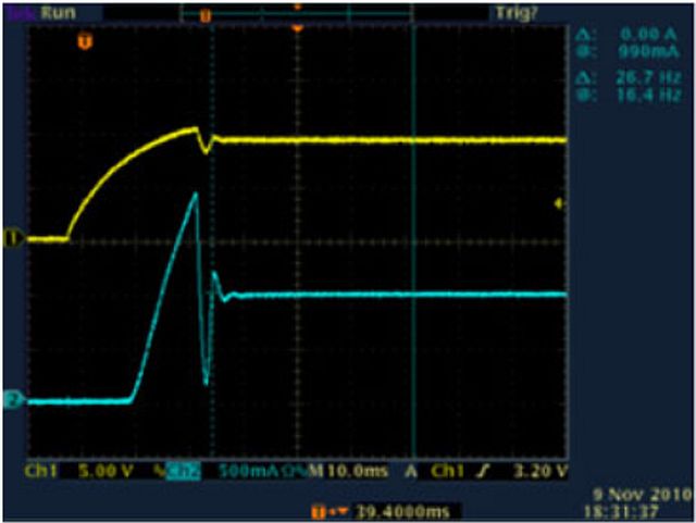
Inrush current is a common phenomenon that overstresses LEDs. An LED can be modeled as a parallel R-C network; as a result, the device is instantaneously a short circuit when a voltage is applied across the device’s terminals. This instantaneous short circuit results in an inrush current, a short-duration startup current, that is of a much greater magnitude than the LED’s steady state operating current. For example, introducing an LED to an energized circuit or “hot switching” the LED may lead to an inrush currents of damaging magnitude. Figure 2 shows that when the switch is open, the voltage at the power supply is maintained at the rated voltage of the LED. As soon as the switch closes, the charge stored at the output of the power supply and the wires flows rapidly into the LED until the power supply starts to regulate. The transient current peak is shown by the blue line in the oscilloscope view in Figure 3(a).


Figure 3. LED turn on voltage (yellow) and current (blue) waveforms when powered by a power supply in the traditional constant voltage (CV) mode (Figure 3a) and the constant current (CC) mode (Figure 3b).

When testing LED designs, engineers typically use a benchtop power supply to drive power to the device precisely while they are taking measurements. Too often, engineers have the settings wrong or they use a power supply that isn’t fully controllable, and end up destroying their devices. But this doesn’t have to happen to you.

A growing trend in power supply design is the addition of a constant current (CC) mode beyond the traditional programmable constant voltage (CV) mode. When a supply operates in the CV mode (Figure 3a), the voltage is regulated while the current may vary. Unlike traditional powers supplies, this new breed of power supplies can be put in a constant current mode independent of the load value. This results in the behavior captured on the oscilloscope in Figure 3b. When the power supply is operating in the CC mode, the current is regulated and supplied to the load while the voltage output may vary. This mode eliminates the need for external controlling circuitry and simplifies the approach to “soft start” a LED. The power supply itself is capable of keeping the current input to the LED under control until the LED reaches the ON-voltage. Removing the possibility of transient inrush current protects the LED from related damage.

Categories Lamp

Is the Future Bright for the California Quality Lamp?

The California Energy Commission (CEC) in conjunction with the California Public Utilities Commission (CPUC) drafted and adopted a document for a new California Quality Lamp, which is currently voluntary. However, beginning in 2014, only LED replacement lamps that meet this new specification will be eligible for rebates in the state. The rationale and drive behind the new specification is to promote quality of light over cheaper, poorer LED replacement lamps that may negatively impact consumer adoption of high efficiency LED light sources.

Development of the new spec was fueled by the historic low adoption rate of poor quality CFL bulbs, which began flooding the market in the 90s when China ramped up mass production of the helical CFL design. Utilities, wanting to reduce energy consumption due to rising oil costs and global warming, encouraged residential consumers to swap out incandescent lamps for CFLs through rebates and buy-downs. Unfortunately, the ultimate market penetration of the CFL was extremely low (roughly 11 percent nationally and 20 percent in California) due to the performance and perceived value of the CFL. Noticeable flaws in CFLs were poor quality of light, the inability to dim, the short life, the flicker, the buzz, the shape, the slow start up in cold weather and the mercury content. This overall lack in comparable product performance drove the consumer back to incandescent bulbs as the primary choice on the basis of both price and quality.

In a nutshell, the perfect storm of events occurred in the US lighting industry demonstrating the importance of all Four P’s of the ‘marketing mix’ – product, price, promotion and place. The results have created a long lasting negative view of CFLs despite significant product improvements in almost all attributes.

The introduction of the California Quality Lamp is positioned by the CEC and CPUC to be the game changer in product performance for energy efficient replacement lamps. Key lessons were learned from the failed CFL marketing approach and, as a result, the voluntary CEC spec focuses primarily on LED light quality, dimmability and longevity while adopting Energy Star performance criteria in other areas such as efficacy. The CEC allows only omnidirectional, floodlamps and spotlights to be qualified as California Quality (refer to summary table of select criteria below).

Product performance is but one of the Four P’s of the traditional marketing mix and understandably, the CEC cannot alone significantly impact the other three factors of price, promotion or the place of sale/method of distribution. So how will the California Quality Lamp succeed and what is the broader plan?

The white paper, “Relighting American Homes with LEDs”, and the DOE study on ‘Lessons Learned’ as cited in Appendix D of the Voluntary California Quality LED Lamp Specification, certainly seem to point toward a more consumer-oriented niche marketing program, collectively known as the Four C’s.

  • Understand and focus on what the Consumer needs rather than the product alone
  • Shift from price to Cost of ownership, i.e. long term value
  • Replace promotion with Communication which includes emphasis on education, environmental impact, advertising and incorporate use of social networks
  • The place and method of distribution should offer Convenience utilizing channels such as the internet and other trends in purchasing

You have the hindsight and the foresight to make the light right! Good luck California, and as always, you lead the way.

Summary of Select Residential California Quality Lamp requirements vs. Energy Star Requirements

Performance Criteria California Quality Lamp Energy Star Lamps
Lamp base and Lamp Shape Limited to Omnidirectional, spotlight and newly defined flood lamps Open to more bases, shapes and decorative lamps
Efficacy Not required Between 40 – 50 lumens/Watt depending on lamp type
Light Output at Elevated Temps Not Required 90% or greater output at elevated temperature
Correlated Color Temp – CCT Only 2700K and 3000K 2700K, 3000K, 3500K, 4000/4100K and 5000K
Color Rendering Index – CRI CRI ≥90 and R9=.50 CRI≥80 and R9=0
Dimming, noise, flicker 100% – 10%, free of noise and flicker No established criteria
Lumen Maintenance Not Required Shall maintain ≥80% of output at 40% of rated life
Rated Life Same as Energy Star Not less than 25,000 hours for residential lamps
Power Factor Pf ≥.9 Pf ≥.7
Electrical Safety Not Required Must Comply with UL1993 and UL8750
Warranty Minimum 5 year Warranty Provide a Warranty period (not specified) and contact information for manufacturer
Categories Lighting

Connect, Protect and Control Your LED Lighting

Thus far in this SSL Blog series, we covered the LED; interconnect of the Chip on Board LED device within a luminaire utilizing a TE Connectivity (TE) scalable or Zhaga compliant socket; and the various device-level interconnects commonly used in lighting applications.  Today, I would like to discuss additional product aspects for consideration in regards to control, circuit protection and power aspects of SSL luminaires.

Control capabilities are increasingly more prevalent within the macro trends of energy efficient and intelligent buildings.  Lighting is a key focus of energy efficiency efforts within a building in that they consume roughly 30 percent of the building’s power consumption. There are significant gains that can be realized by controlling light levels. Adding intelligence to lighting is a key element to a comprehensive building plan to conserve energy.

Traditionally, the most practical and cost effective lighting control is the common wall switch. Its fault is that incorporates a human element and we all know how variable this element can be. To remove the human from the control equation, building intelligence needed to evolve to a sense, communicate and control environment via available technology. A simple implementation such as installing an occupancy sensor that senses movement in the room and directly controls a light fixture can offer immediate energy savings. Tie this sensor into a network of other occupancy sensors as well as daylight and ambient light sensors, and suddenly the building is “intelligently” able to react to its occupants and environment.

This effect of increasing levels of control required within building lighting systems ripples through to new requirements for components used within the systems.  For example, TE’s well established RT series relays have been on the market for years but needed to be further refined to meet the increasing demands of switching the more energy efficient fluorescent and SSL fixtures coming to market.  The high input current spikes characteristic of today’s drivers drove a radically new switching technology that was incorporated into TE’s RTX relay and new contact structure built into the RT1 Inrush Power relay.

The electronification of lighting and related controls also increased susceptibility to potentially damaging surges caused by ‘dirty power’ and / or lightning. While traditional incandescent lamps were relatively immune to this, SSL luminaires require some level of circuit protection to protect the end product from power fluctuations and surges.  A fuse offers some level of protection. However, fuses are typically “once & done” devices that render the fixture inoperable after an event. A better solution is a self-resetting device such as TE’s 2Pro AC device. The 2Pro AC device offers designers an integrated, self-resetting device that protects sensitive downstream electronics against damage from overcurrent and overvoltage events. By combining a PPTC (polymeric positive temperature coefficient) device and a thermally enhanced MOV (metal-oxide varistor) into one package, a more robust and more easily integrated level of protection can be included into lighting control products.

Another less often discussed topic within controls is conducted emissions and susceptibility. With the increasing use of microprocessors throughout lighting control systems, electrically noisy power systems can wreak havoc on a control network. Increasing use of power line (data/broadband) communication within a building can further fuel a noisy power environment for building controls. Conversely, particularly noisy control devices such as drivers and power supplies that run at higher frequencies and harmonics can often induce noise into the building power system and affect other electronic devices. The latter is especially weighty in hospital and other medical environments where such noise could have catastrophic results given the right conditions. Conducted emission filters such as TE’s FB & VB series are increasingly used in these applications to both protect devices from incoming conducted RFI and likewise limit any outgoing emissions on the power lines.

There’s no doubt the lighting environment is changing. This is visually evident throughout the world. In a less obvious manner, the environment is changing fixture and system designs and is spawning a host of new supporting products. The end result must be to ensure that the consumer gets the best, most controllable light possible that meets the adage, “The best light is the one you don’t notice”.

I’ve covered a few new topics above that are changing the face of lighting and lighting controls. I’m interested in hearing about other challenges and issues you’re seeing. If you have a minute, send me a note with your thoughts and comments. Please send me an email at plieffrig@te.com.